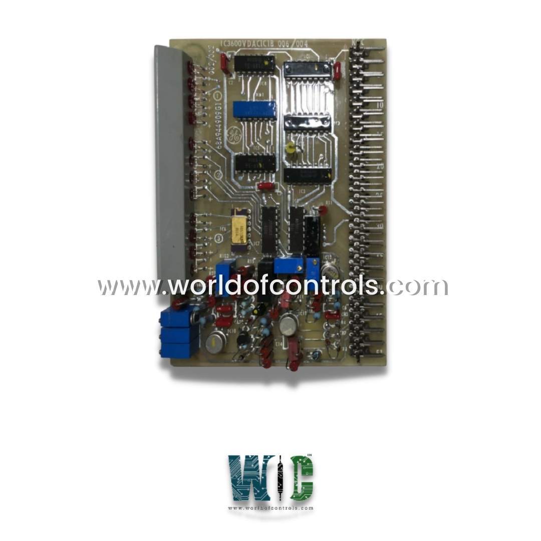
World Of Controls understands the criticality of your requirement and works towards reducing the lead time as much as possible.
IC3600VDAC - Digital to Analog Converter Board is available in stock which ships the same day.
IC3600VDAC - Digital to Analog Converter Board comes in UNUSED as well as REBUILT condition.
To avail our best deals for IC3600VDAC - Digital to Analog Converter Board, contact us and we will get back to you within 24 hours.
Part Number: IC3600VDAC
Manufacturer: General Electric
Country of Manufacture: United States (USA)
Series: Mark I and II
Function: Variable Digital-to-Analog Converter
IC3600VDAC is a variable digital-to-analog converter developed by GE. It is part of the GE Speedtronic Mark I and II control system. The VDAC (Variable Digital-to-Analog Converter) card is a component in the digital setpoint system used for generating programmable analog signals. This card is essential for applications requiring precise speed or load control. It works in conjunction with the SSLD (Speed/Load Setpoint Logic and Drive) card and other associated control signals.
The counter's operation is finely tuned by the system’s steering logic, providing highly responsive performance for dynamic control applications.
The card features an integrated Digital-to-Analog (D/A) converter that transforms the digital counter output into a precise analog voltage signal known as SAOUT.
Adjustable Output Ranges:
This flexibility ensures compatibility with a variety of control scenarios and turbine specifications.
This capability is essential for predefining operational setpoints, enabling rapid and accurate system configuration changes.
The card provides MM1, MM2, and MM3 output signals that indicate when the counter reaches its full or empty states:
The analog output (SAOUT) feeds directly into the SSLD card. The SSLD card:
An onboard comparator circuit compares the digital setpoint output with a reference signal. Based on this comparison:
WOC has the largest stock of Mark I and II Spares and we can repair your faulty spares with a warranty. WORLD OF CONTROLS can also supply unused and rebuilt components backed by a warranty. Our team of experts is available round the clock to support your urgent needs related to critical spares, Contact us.
What is IC3600VDAC?
It is a Digital to Analog Converter Board and is part of the GE Speedtronic Mark I and II gas turbine control system.
What is the primary function of the card?
The primary function of the card is to convert digital setpoints into programmable analog signals for speed or load control. It provides precise control by generating analog outputs based on digital inputs.
How does the card's counter work?
The card contains a 12-bit reversible counter that can count up or down. The direction of counting is controlled by the DN/UP input while the ENAB input must be set to logic 0 for counting to occur. The CCP input sets the rate at which the counter increments or decrements.
How does the card indicate the counter’s status?
The counter’s status is indicated by twelve LEDs on the card, which reflect the current output of the counter.