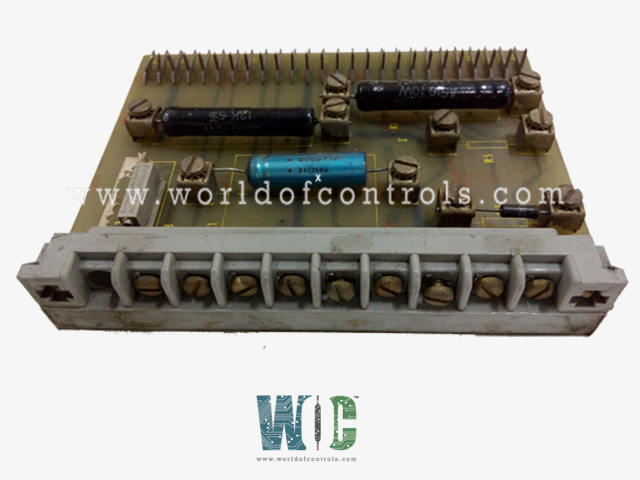
World Of Controls understands the criticality of your requirement and works towards reducing the lead time as much as possible.
IC3600TCBA1 - SCR Drive Control Card is available in stock which ships the same day.
IC3600TCBA1 - SCR Drive Control Card comes in UNUSED as well as REBUILT condition.
To avail our best deals for IC3600TCBA1 - SCR Drive Control Card, contact us and we will get back to you within 24 hours.
SPECIFICATIONS:
Part Number: IC3600TCBA1
Manufacturer: General Electric
Series: Mark I & II
Function: SCR Drive Control Card
Input Signals: �10 V
Output Signals: 0�10 V
Firing Angle Control: 0��180�
Response Time: < 1 second
Input Voltage Range: 0�10 VDC
Isolation Voltage: 1500 V RMS
Power Supply: +24 VDC
Alarm Threshold Adjustment: 0.5�9.5 V
Power Consumption: 2.5 W
Mounting: Rack-mounted
Operating Temperature: -20�C to +70�C
Number of Red LEDs: 3
Dimensions: 15.2 cm � 17.8 cm
Availability: In Stock
Product of Origin: USA
FUNCTIONAL DESCRIPTION:
IC3600TCBA1 is a SCR Drive Control Card manufactured and designed by General Electric for the Mark I & II Series used in gas turbine control systems. The SCR Drive Control Card functions as the primary interface and control module for regulating SCR-based power conversion in high-power drive systems. It receives analog or digital input signals representing desired voltage, current, or excitation setpoints, and conditions these signals for accurate SCR gate triggering. The card provides isolation, filtering, and attenuation of high-voltage feedback from the SCR bridge, converting it into low-level control signals compatible with the system�s control logic. It executes precise firing angle control of the SCRs, modulating conduction intervals to regulate output voltage, current, or excitation with high fidelity. Integrated jumpers, transformers, and protective circuitry allow adaptation to varying system voltages and configurations, while the card interfaces with instrumentation, power supply, and ancillary control modules to maintain stable, synchronized operation of motors, generators, or turbine excitation systems.
SIGNAL CONDITIONING AND ISOLATION:
The SCR Drive Control Card accepts multiple analog and digital input signals corresponding to system setpoints, including voltage reference, current reference, excitation demand, and speed or power control signals. Incoming signals are first routed through precision attenuation networks to scale high-magnitude analog voltages or currents into levels compatible with the card�s processing circuitry. Filtering circuits, typically comprising low-pass RC networks or active filters, remove high-frequency noise, transient spikes, and switching interference from the SCR bridge, ensuring that only clean, stable signals reach the control logic.
Electrical isolation is provided between the high-voltage power stage and the low-voltage control circuitry, commonly implemented using opto-isolators, isolation transformers, or differential amplifiers, to prevent ground loops and protect sensitive components from voltage surges. The card may also include signal clamping and overvoltage protection devices to safeguard against transient faults or SCR bridge disturbances.
SCR FIRING ANGLE CONTROL:
The SCR Drive Control Card generates and manages the precise gate firing signals required to control the conduction of the SCRs in the power stage. Based on analog or digital input setpoints, the card computes the optimal firing angle for each SCR within the AC cycle, taking into account real-time feedback from voltage, current, and excitation sensing circuits. The firing angle calculation is performed using either analog phase control circuitry or digital logic processors, ensuring microsecond-level timing accuracy for each SCR pulse.
The control card outputs isolated gate drive pulses with controlled amplitude, duration, and phase relative to the AC supply, directly modulating the conduction intervals of the SCRs. This phase-angle control regulates the effective voltage and current delivered to the load, enabling precise control of motor speed, generator excitation, or power output. The card continuously monitors load and SCR bridge conditions to dynamically adjust firing angles in real time, maintaining stable operation under fluctuating loads, sudden disturbances, or system transients.
INTERFACE AND INTEGRATION:
The SCR Drive Control Card provides a robust interface between the high-power SCR stage and the system�s supervisory control and instrumentation modules. It incorporates configurable jumpers, tap-adjustable transformers, and programmable isolation networks to accommodate a range of input and output voltage levels, frequency ranges, and system configurations. This allows the card to adapt to varying power supply characteristics, load requirements, and control architecture designs without requiring extensive hardware modification.
At WOC, we maintain the most comprehensive inventory of replacement parts for GE Speedtronic Turbine Control Systems, including both unused, warranty-backed boards and expertly refurbished modules designed to meet rigorous operational standards. Beyond providing replacement components, we offer specialized repair and restoration services for damaged or malfunctioning boards, ensuring reliable performance and extending the service life of critical turbine control equipment. Our team of highly skilled engineers and technicians delivers 24/7 support, assisting with OEM requirements, technical troubleshooting, system upgrades, and automation solutions to minimize downtime and optimize overall system efficiency. Whether you require detailed component specifications, urgent repair services, or guidance on system integration, we are ready to provide prompt, dependable assistance via phone or email, helping you maintain continuous, high-performance operation.
What is the function of an SCR Drive Control Card?
The SCR Drive Control Card regulates the firing of SCRs in high-power drive systems, converting control setpoints into precise gate pulses. It ensures accurate phase-angle control to maintain stable voltage, current, or excitation output. The card also provides signal conditioning, isolation, and diagnostic feedback for reliable system operation under industrial conditions.
How does the card control SCR conduction?
The card calculates the optimal firing angle for each SCR based on input setpoints and real-time feedback. It generates isolated gate drive pulses with precise timing to control conduction intervals. By modulating SCR conduction, the card regulates output power, ensures load stability, and minimizes harmonics in the system.
What types of signals does the card accept?
It accepts both analog and digital input signals, typically representing voltage, current, or excitation setpoints. Inputs are conditioned through filtering, attenuation, and isolation circuits to ensure accurate processing. This allows safe interfacing between high-power SCR circuits and low-level control logic.