World Of Controls understands the criticality of your requirement and works towards reducing the lead time as much as possible.
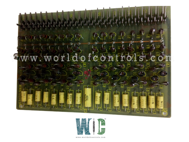
IC3600LIVA1A - Logic Inverter Printed Circuit Board is available in stock which ships the same day.
IC3600LIVA1A - Logic Inverter Printed Circuit Board comes in UNUSED as well as REBUILT condition.
To avail our best deals for IC3600LIVA1A - Logic Inverter Printed Circuit Board, contact us and we will get back to you within 24 hours.
SPECIFICATIONS:
Part Number: IC3600LIVA1A
Manufacturer: General Electric
Series: Mark I & II
Product Type: Logic Inverter Printed Circuit Board
Number of Inputs: 8
Accuracy: 0.25% at 25 degrees Celsius
Operating Modes: Current Mode or Voltage Mode
Input Data: 16-bit Input Data
Update Rate: 13 ms all channels
Backplane Current Consumption: 15 mA at 5V, 120 mA at 3.3V
Voltage Range: -10 to 10 Volts DC
Resolution at 0-20 mA: 5 microamps
Input Impedance: 250 ohms
Frequency: 50 to 60 Hertz
Internal Power Consumption: 120 mA
Availability: In Stock
Weight: 1.5 Kg
Country of Origin: United States
FUNCTIONAL DESCRIPTION:
IC3600LIVA1A is a Logic Inverter Printed Circuit Board manufactured and designed by GE Mark II Series as part of the GE Speedtronic Gas Turbine Control Systems. It is designed to support the logical decision-making framework essential for safe and efficient turbine operation. These early-generation Speedtronic systems, developed by General Electric, were engineered with a focus on reliability, simplicity, and hardwired logic—using modular PCBs like the logic inverter to carry out fundamental control functions. The primary role of the logic inverter board is to receive digital input signals and output their logical inverse, a necessary operation for controlling sequences, implementing safety interlocks, and driving conditional outputs throughout the turbine start-up, shutdown, and load management processes.
INSTALLATION:
The board is typically mounted in a modular control rack within the turbine’s control panel, where it interfaces with other logic, relay, and sequencing boards via a card-edge connector and backplane wiring system. This design ensures standardized connectivity across various functional modules, facilitating seamless signal flow and communication throughout the Speedtronic logic architecture. The card-edge connector allows for rapid installation and removal without soldering or rewiring, minimizing downtime during maintenance or replacement. Once inserted into its designated slot, the IC3600LIVA1A board establishes both power and signal connections through its gold-plated edge contacts, ensuring low resistance and reliable performance under varying electrical loads. The proper seating of the board in the backplane is essential to maintaining circuit continuity, preventing logic errors, and upholding system reliability. Additionally, the modular design allows for easy troubleshooting by isolating faulty boards without impacting the entire control system—an important feature in mission-critical applications like gas turbine operation.
OPERATIONS:
Its primary function is to invert logic signals, converting high-level digital inputs (typically +5V DC, logic “1”) into low-level outputs (0V, logic “0”) and vice versa. This logical inversion is critical in various control sequences where inverse signaling is required to initiate, block, or condition a specific operation within the turbine system.
Internally, the board uses transistor-transistor logic (TTL) circuits configured in NOT gate arrangements. These electronic components process input signals and output their logical complement with high-speed switching and minimal propagation delay. This makes the board suitable for real-time turbine control environments, where timing accuracy and deterministic signal behavior are paramount.
WOC has the largest stock of OEM Replacement Parts for GE Speedtronic Control Systems. We can also repair your faulty boards and supply unused and rebuilt boards backed up with a warranty. Our team of experts is available around the clock to support your OEM needs. Our team of experts at WOC is happy to assist you with any of your automation requirements. For pricing and availability on parts and repairs, kindly contact our team by phone or email.
What are the common signs of failure in a logic inverter board?
Common signs of a faulty logic inverter board include unexpected control behavior, logic sequence failures, inactive or stuck interlocks, and the appearance of false alarms or trips. In some cases, the outputs may remain fixed regardless of input changes, indicating a failed component such as a transistor or logic gate.
How does the logic inverter function electrically within a control system?
Electrically, a logic inverter board uses NPN transistors or logic gates (such as NOT gates or inverters from IC families like 7404) to invert input voltage signals. For example, when a logical HIGH (typically +5V) is applied to the input pin, the output circuit is driven LOW (0V), and vice versa. This inversion supports system logic control that depends on the complementary state of input signals.
Can logic inverter boards operate at different logic voltage levels?
Most turbine-related inverter boards are designed for 5V TTL levels; however, variants exist for 3.3V or even 24V industrial logic. It's critical to ensure voltage compatibility between the inverter board and interfacing systems. Level-shifting may be required when mixing logic families or when connecting to PLCs or microcontrollers with different voltage tolerances.