SPECIFICATIONS
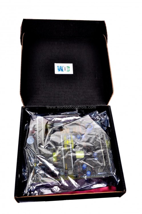
Part Number: DS200TCCBF1BDA
Manufacturer: General Electric
Series: Mark V
Temperature -30 to + 65 oC
Altitude: 2000 m maximum
Relative humidity: 5 to 95 percent non-condensing
Surge: Designed to ANSI C37.90.1
Repair: 3-5 Days
Product type: Software EPROM Set
Country of Manufacture: United States (USA)
Functional Description
DS200TCCBF1BDA is a software EPROM set developed by GE under Mark V control system. EPROM in controllers provides a stable and reliable foundation for the system's operation, safeguarding vital data and ensuring the continuity of control processes in various industrial applications.
System Master Trip Circuit
- One of the important protective functions associated with a turbine control system is the System Master Trip Circuit. Its purpose is to initiate a turbine trip when a valid condition requires the turbine to be removed from operation.
- The Master Trip Circuit is designed with reliability and redundancy in mind. It works with input signals, relay logic, DC power sources, and output circuits to provide a dependable path for initiating protective action.
- A turbine trip can be initiated by conditions detected directly by the Mark V or by signals originating from external or remote equipment.
Inputs to the Mark V
- Signals that can initiate a turbine trip may originate from either hardwired inputs or remote sources, depending on the system configuration.
- Hardwired trip inputs are commonly arranged as contact-open-to-trip circuits. This arrangement provides a direct electrical path between field devices and the turbine control system.
- The associated relay devices are commonly identified using ANSI device numbering, where the number 4 is associated with a master trip or primary control relay function in turbine protection applications.
- When a trip condition occurs, the appropriate input circuitry changes state and the Mark V system processes the condition according to its programmed and hardware-based protection logic.
Mark V Master Trip Output
- After receiving and validating a trip condition, the Mark V system controls the Master Trip Circuit to initiate the required turbine shutdown or trip action.
- The output portion of the circuit incorporates redundant relay arrangements to improve reliability and reduce the possibility of an unintended turbine trip caused by a single component failure.
- The relay coils are arranged in association with the available DC power buses. One group is connected with the positive DC bus, while another is associated with the negative DC bus.
- This arrangement creates multiple electrical paths and provides a degree of redundancy within the master trip architecture.
Redundant Relay Configuration
- Redundancy is a key principle in turbine protection systems because both failure to trip when necessary and unnecessary turbine trips can have significant consequences.
- The Master Trip Circuit therefore uses redundant relay elements and associated contacts to increase system reliability.
- The relay arrangement is designed so that the failure of a single relay coil does not automatically produce a false turbine trip. The associated hardware contacts are arranged so that the remaining operational relay can maintain the required circuit state.
- This protects against certain single-component failures while allowing the system to continue operating normally.
Fail-Safe Trip Architecture
- The Master Trip Circuit uses a fail-safe approach to turbine protection. Its architecture is designed to distinguish between normal operating conditions, component failures, and genuine trip commands.
- The redundant relay arrangement helps ensure that a single failed relay does not unnecessarily initiate a turbine trip.
- At the same time, the circuit is configured so that a legitimate trip command can remove the required relay energization and initiate the protective action.
- This balance between availability and protection is particularly important in turbine control systems. The system must remain available during normal operation while still being capable of responding quickly when a genuine hazardous condition is detected.
Trip Logic
- The Master Trip Circuit uses relay logic in combination with the Mark V control architecture to determine when a turbine trip should occur.
- A key aspect of the circuit is that the trip logic requires the appropriate de-energization of the redundant relay paths before the master trip condition is established.
- In the described architecture, both relay coils associated with the same DC bus must be de-energized to produce the required trip condition. This arrangement reduces the likelihood that a single relay failure or isolated electrical fault will result in an unnecessary turbine trip.
- The redundant design therefore provides an additional level of discrimination between a component failure and an actual turbine trip command.
Relationship Between Software and Hardware Protection
- The Software EPROM Set forms part of the software side of the Mark V control architecture, while the Master Trip Circuit represents an important part of the hardware-based protection arrangement.
- The two work within the overall turbine control system but perform different roles.
- The software can process turbine operating information, alarms, sequencing conditions, and programmed protective logic. The hardware trip circuitry provides dedicated electrical paths and relay logic for critical protective actions.
- This combination of software-based control and hardware-based protection helps the Mark V provide comprehensive turbine management while maintaining independent and redundant protection functions.
Importance of Redundancy in Turbine Protection
Turbines operate under demanding mechanical, thermal, and electrical conditions. A control-system failure can potentially result in equipment damage, operational interruption, or safety concerns. For this reason, turbine protection systems are designed with redundancy wherever practical. The Master Trip Circuit's redundant relay arrangement helps provide:
- Improved protection against single-component failures
- Reduced risk of false turbine trips
- Greater reliability of the trip command
- Independent electrical paths
- Improved availability during normal operation
- More dependable response to genuine trip conditions
The exact circuit implementation can vary according to the turbine application and Mark V system configuration.
WOC is happy to assist you with any of your GE requirements. Please contact us by phone or email for pricing and availability on any parts and repairs.
FREQUENTLY ASKED QUESTIONS
What is DS200TCCBF1BDA?
It is a software EPROM set developed by GE.
Can the Mark V system continue operating if there is a fault in one of the analog inputs?
Yes, the system can continue to operate even if there is a fault in one of the analog inputs. It uses the median signal from the R, S, and T controllers to continue performing control and protection calculations, ensuring ongoing turbine operation.
What are the benefits of using median signal processing in the Mark V system?
Using median signal processing helps the Mark V system to maintain accurate control and protection even if one of the inputs is faulty. This redundancy ensures that the system can continue to operate safely and reliably, minimizing the risk of incorrect calculations due to a single faulty input.
How are the voltage signals distributed within the Mark V system?
The voltage signals generated from the burden resistor are internally parallel wired using ribbon cables to the R, S, and T controllers (or just the R controller in simplex applications). This parallel distribution allows for effective discrepancy detection and median signal processing.