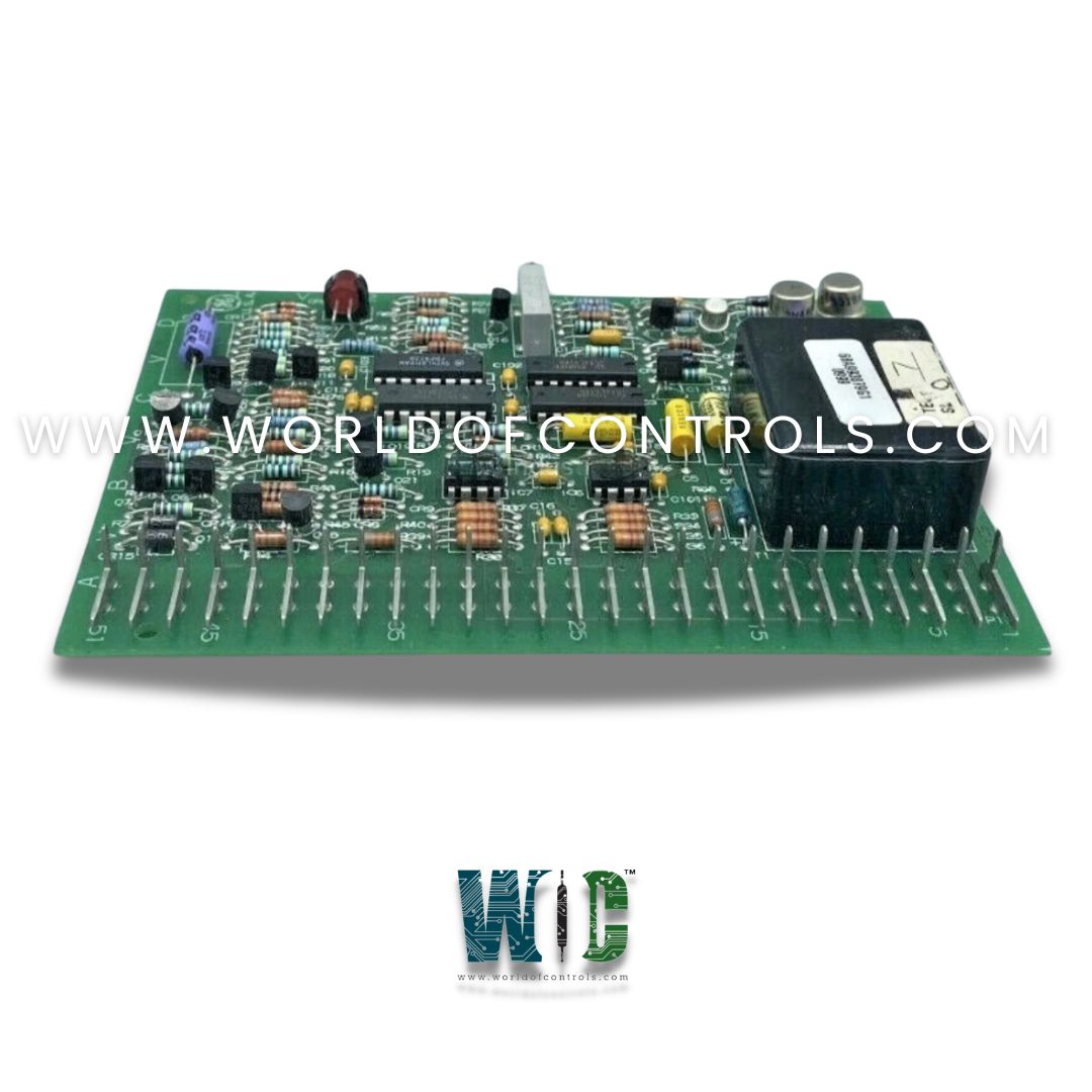
SPECIFICATIONS
Part No.: IC3600EPSU1L1C
Manufacturer: General Electric
Country of Manufacture: United States of America (USA)
Product Type: Power Supply Control Board
Availability: In Stock
Series: VersaMax
Functional Description
IC3600EPSU1L1C is a Power Supply Control Board developed by GE. It is a part of Mark I and Mark II Speedtronic systems. It manages DC-to-AC power inversion through a time-ratio controlled inverter, handling input voltages between 95-150V.
Functional Role in the System
- This control card interfaces with the primary side of a time-ratio controlled transistor inverter, enabling efficient conversion of DC to AC power. Time-ratio control is crucial because the input DC voltage can vary widely from 95V to 150V. The card manages the transition between the A-side and B-side of the inverter, ensuring balanced operation.
- It also features a current limiting circuit that prevents the inverter from exceeding safe operating conditions by shutting it down when current saturation is detected. The inverter is reactivated via control pulses from a secondary card, which regulates voltage on one of the inverter’s secondary windings. The inverter typically operates with a pulse rate of 700–800 pulses per second, corresponding to 350–400 Hz switching frequency.
Key Functional Blocks
- Power Supply Section: DC input is applied through an external resistor and Zener diode to terminal P51. Components Q1, Q2, and T1 form a self-oscillating inverter (SKHZ type). The center-tapped secondary of T1 is rectified to generate internal P8, N8, and PS buses for powering the board. An isolated winding also provides power to essential logic circuits on the secondary side of the power inverter, ensuring isolation between primary and secondary sides.
- Current Limit Circuit: This section monitors the current drawn by the external power transistors. Resistors R33 to R35 sample the current via voltage drop across current-sharing resistors. These voltages are fed into the CLA comparator — a precision differential amplifier integrated with a switching transistor. A reference voltage is set using a Current Limit Potentiometer, typically between 1.2 to 1.9 volts. If the sensed voltage exceeds the reference, CLA drives output low (zero) on the OCL (Over Current Limit) line, signaling the logic to shut down the inverter. Similarly, CLB performs the same function for the B-side inverter. Q16 momentarily increases the current limit by 50% for 30 microseconds to allow initial inrush current without tripping the limit. IA and IB terminals provide current monitoring signals for oscilloscope observation.
- Sequencing Logic: A truth table (referenced on sheet 3.2) governs how flip-flops control the switching states. Logic signals XX and OX form a flip-flop which controls the inverter enable line (X). A secondary flip-flop (Y) acts as a binary counter, changing state each time X transitions to zero. OCL signal forces X to zero in case of current limit violation, thereby shutting down the inverter. An external pulse (PUL) sets X to one, restarting inverter operation unless a protective condition persists. Combinations of X and Y (e.g., OXY, OXOY) determine whether the A-side or B-side power transistors are to be driven.
- Base Drive Circuitry: Base drive logic controls the power transistor switching. When logic signal BAX is high, it turns on transistors Q10 and Q18, delivering 90–100 mA to the base of the power transistor. Upon BAX going low, OBAX goes high, activating Q21, which shorts the base to ground for rapid turn-off. Typical turn-off time for the power transistor is 10–15 microseconds, essential for minimizing switching losses and heat buildup.
- Protective Features: In addition to current limit shutdown, the card has logic to prevent reactivation under fault conditions. The OCL line serves as a universal interrupt to stop inverter operation during dangerous electrical conditions. Protective states inhibit the response to external restart pulses, ensuring the inverter only operates under safe conditions.
The WOC team is always available to help you with your Mark I and II requirements. For more information, please contact WOC.
Frequently Asked Questions
What is IC3600EPSU1L1C?
It is a Power Supply Control Board developed by GE under Mark I and II series.
What voltage range does the board handle?
It operates with a variable input DC voltage ranging from 95 to 150 volts, requiring time-ratio control to maintain stable operation.
How does the board protect the inverter?
It includes current limit circuitry that shuts down inverter operation when current exceeds safe thresholds, and prevents reactivation until conditions normalize.
How is the inverter turned on or off?
Turned on via pulses from the card.Turned off automatically by current limit protection or manually via logic inputs.
