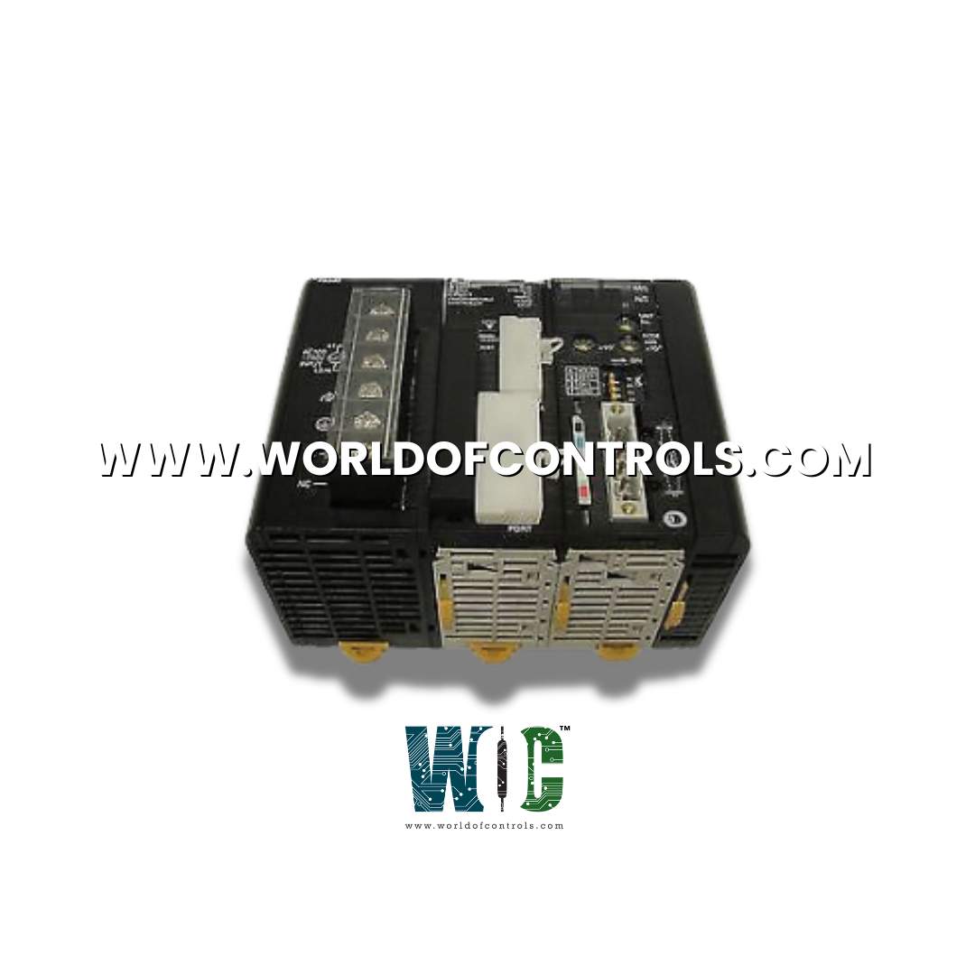
IS210TTSAG1A - Trip Solenoid Interface Terminal Board

IS210TTSAG1A - Trip Solenoid Interface Terminal Board IS210TTSAG1A - Trip Solenoid Interface Terminal Board

World Of Controls understands the criticality of your requirement and works towards reducing the lead time as much as possible.

IS210TTSAG1A - Trip Solenoid Interface Terminal Board is available in stock which ships the same day.

IS210TTSAG1A - Trip Solenoid Interface Terminal Board comes in UNUSED as well as REBUILT condition.

To avail our best deals for IS210TTSAG1A - Trip Solenoid Interface Terminal Board, contact us and we will get back to you within 24 hours.

SPECIFICATIONS

Part Number: IS210TTSAG1A
Manufacturer: General Electric
Series: Mark VI
Product Type: Trip Solenoid Interface Terminal Board
Repair: 3-5 days
Maximum applied V dc: 145 V
Resistor tolerance: 5 percent
Minimum solenoid impedance: 0 ohm
Availability: In Stock
Country of Manufacturer: United States (USA)

Functional Description

IS210TTSAG1A is a trip solenoid interface terminal board developed by General Electrics. It is a part of Mark VI control system. It is a component in the electrical control and protection of systems, particularly those involving trip solenoids. This board is designed to efficiently handle and manage the power requirements associated with trip solenoids, and it does so through a set of four power resistors arranged in a specific configuration to accommodate bipolar currents. Its power resistor configuration, pluggable barrier terminal strips, and robust power ratings make it a reliable and versatile component in various systems, including those with stringent electrical demands. Furthermore, its compact physical design offers space-saving advantages without compromising on performance, making it a valuable asset in both large and small-scale applications.

Features

  • Power Resistor Configuration: The board boasts a carefully configured arrangement of four power resistors. These resistors are strategically designed to support the flow of bipolar currents, which are currents that periodically change direction. This configuration is crucial for accommodating the specific electrical characteristics of trip solenoids.
  • Pluggable Barrier Terminal Strips: All connections are facilitated through pluggable barrier terminal strips. This design choice simplifies the installation and maintenance process, allowing for easy and secure connections without the need for soldering or complex wiring.
  • Functional Equivalent to 194B5725 Servo Module: The functionally equivalent to the 194B5725 Servo Module, but it boasts a smaller physical design. This means that it delivers the same level of performance and functionality as the larger module while offering space-saving advantages. This compact design can be particularly beneficial in situations where space constraints are a concern.
  • Robust Power Ratings: The power ratings are designed to be more than sufficient to withstand demanding electrical conditions. It can handle a high DC line voltage of up to 145 V DC, making it suitable for a wide range of applications where higher voltages are involved.
  • Zero Solenoid Impedance Consideration: The board is engineered to handle situations where trip solenoids exhibit zero impedance. Zero impedance implies that there is no resistance to the flow of current. The board's design accounts for this scenario, ensuring that it can manage the electrical load even under challenging conditions.

Installation

The installation of trip solenoid coils through the TTSA is a crucial step in ensuring the reliable and safe operation of a system. TTSA is designed to efficiently manage the power and electrical connections required for trip solenoids. Here's a comprehensive guide to the installation process:

  • Determine Solenoid Coil Locations: Before installation, identify the locations where the trip solenoid coils will be placed. The number of solenoid coils can vary, but it is designed to accommodate up to four coils. Ensure that the chosen locations are accessible and strategically positioned to respond to specific conditions or events that require emergency shutdowns or other critical actions.
  • Prepare Solenoid Coils: Prepare the trip solenoid coils for installation. This includes verifying that each coil is in good working condition, with all connections, wires, and components intact. Ensure that the coils are compatible with the system's voltage requirements and that they have the appropriate impedance characteristics.
  • Mount TTSA: Securely mount the board in its designated location within the system. Ensure that it is properly secured and positioned to allow for efficient wiring and connections.
  • Access Barrier Terminal Strips: Locate the pluggable barrier terminal strips on the board. These terminal strips are the points of connection for the trip solenoid coils.
  • Wire Solenoid Coils: Connect the trip solenoid coils to the barrier terminal strips on the board. Ensure that the wiring is done correctly, with the appropriate wires securely fastened to their designated terminals. Follow a color-coding or labeling scheme if applicable to maintain organization and ease of troubleshooting.
  • Verify Polarity: Verify the polarity of the solenoid coils. Ensure that the coils are correctly connected to provide the desired bipolar current flow. Incorrect polarity can affect the solenoid's response and may lead to malfunction.
  • Check Electrical Connections: Inspect all electrical connections to ensure they are secure and free from any loose wires or potential short circuits. Properly tighten terminal screws or connectors to prevent any intermittent electrical issues.
  • Connection to Tripping Boards: Depending on the specific system configuration, connect the trip solenoid coils to the appropriate tripping boards. These boards are responsible for initiating trip actions when necessary.
  • Finalize Wiring: Once all connections are made, double-check the wiring to ensure it matches the intended setup. Verify that each solenoid coil is correctly wired and connected to its respective tripping board.
  • Test the system: After installation, perform system testing and commissioning. Test the trip solenoids to confirm that they operate as expected when triggered by the system's control or protection mechanisms.

Attributes

  • Maximum Applied Voltage: The maximum applied Vdc, or direct current voltage, to the terminal board is set at 145 V. Operating within this limit prevents voltage spikes or overloads that could compromise the integrity of the system.
  • Resistor Tolerance: The resistor tolerance, set at 5 percent, ensures that resistor components within the system maintain accuracy within a specified range. This tolerance level accounts for potential variations in resistor values due to manufacturing processes or environmental factors.
  • Minimum Solenoid Impedance: The minimum solenoid impedance, specified as 0 ohm, establishes the lower limit for the impedance of the solenoid coils connected to the terminal board. This threshold ensures that the solenoids operate within safe impedance ranges, preventing excessive currents or voltage drops.

WOC has the largest stock of Speedtronic control spares. Please contact our staff by phone or email for pricing and availability on any parts and repairs


FREQUENTLY ASKED QUESTIONS

What is IS210TTSAG1A?
It is a trip solenoid interface terminal board developed by General Electrics.

What is the purpose of applying fixed 125 V nominal DC power to terminals 11 and 02?
The application of fixed DC power to these terminals serves as the primary power source for the solenoid coil circuit. It provides the electrical energy required for the solenoid to function.

How is running current achieved in the solenoid coils, and what is its significance?
Running current in the solenoid coils is achieved by applying positive DC voltage to the TS-POS terminal and negative DC voltage to the TS-NEG terminal. This reverse current is used when it is necessary to maintain a specific level of current in the coils for operational purposes, not just for tripping.

What is the practical application of these calculations in solenoid systems?
These calculations are essential for determining the current levels in solenoid coils, both for tripping and running conditions. Understanding and controlling these currents is crucial for the proper operation of solenoid-based systems, particularly in scenarios where precise control and safety are paramount.

Are there variations in the voltage levels or coil impedance that could affect these calculations?
Yes, variations in voltage levels and coil impedance will directly impact the calculated currents. It's essential to consider these factors carefully when designing or troubleshooting solenoid systems to ensure they operate as intended.