SPECIFICATIONS
Part Number: IS210TRPLH1A
Manufacturer: General Electric
Series: Mark VI
Product Type: Primary Protection Trip Output Board
Repair: 3-5 days
Size: 17.8 cm wide x 33.02 cm high
Availability: In Stock
Country of Manufacturer: United States (USA)
Functional Description
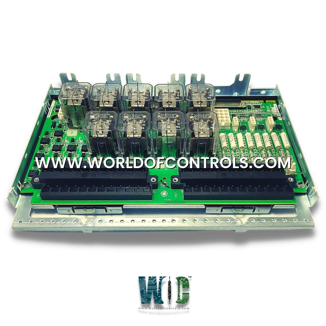
IS210TRPLH1A is a Primary Protection Trip Output Board developed by General Electrics. It is a part of Mark VI control system. The terminal board plays a critical role in safeguarding large steam turbines by serving as the primary overspeed protection mechanism. Controlled by the turbine I/O controller, TRPL comprises nine magnetic relays organized into three voting circuits, facilitating seamless interfacing with three trip solenoids, known as the Electrical Trip Devices (ETD). Collaborating closely with the TREL terminal board, TRPL forms the primary and emergency sides of the interface to the ETDs, ensuring comprehensive protection against potential overspeed incidents.
Features
- Overspeed Protection: Primary function is to detect and respond to overspeed conditions in large steam turbines, preventing potential damage.
- Relay Configuration: The nine magnetic relays are strategically arranged in three voting circuits, enhancing reliability and redundancy in the overspeed protection system.
- Interface with Trip Solenoids: Facilitates seamless interfacing with trip solenoids, which act as the final safeguard against overspeed incidents by initiating trip actions when necessary.
- Collaboration with TREL: TREL and TRPL work in tandem, similar to TRPG and TREG in gas turbine applications, to ensure the effectiveness of overspeed protection mechanisms.
Wiring and Configuration
- Trip Solenoid Connection: Up to three trip solenoids can be connected between the TREL and TRPL terminal boards, with TREL providing the positive side of the 125 V dc supply and TRPL providing the negative side.
- Manual Emergency Stop: Provision is made for wiring in two manual emergency stop functions, further enhancing safety measures and providing operators with additional control over turbine operation in emergencies.
Installation Procedure
- Trip Solenoid Wiring: The three trip solenoids are wired directly to the first I/O terminal block on the TRPL board. This direct connection facilitates efficient communication and control over the trip solenoids, crucial for responding to overspeed conditions promptly. Trip solenoid power is supplied through plugs JP1, JP2, and JP3, ensuring a reliable power source for the operation of these critical components.
- Emergency Stop Configuration: The primary emergency stop and, if applicable, the optional secondary emergency stop are wired to the second terminal block on the TRPL board. This setup provides redundant safety measures, allowing for swift shutdown actions in emergencies. Using a jumper, terminals 9 and 11 must include the PTR3 trip, ensuring proper functionality of the trip mechanism. If a second emergency stop is required, wiring to terminals 46 and 47 is necessary, and the jumper must be removed to facilitate this additional safety feature.
- Wiring Configuration: The wiring connections must adhere to specific configurations outlined in GE guidelines or schematic diagrams. Adhering to these guidelines ensures proper alignment and functionality of the terminal board within the overspeed protection system.
Configuration
- Jumper Configuration
- PTR 3 Trip Inclusion: Terminals 9 and 11 on the terminal board must be connected using a jumper to include the PTR 3 trip. This configuration ensures that the overspeed protection system operates effectively and accurately detects and responds to overspeed conditions.
- Manual Emergency Stop: If only one manual emergency stop is required, a jumper must be placed on terminals 46 and 47. This jumper configuration enables the functionality of the primary emergency stop, providing operators with a means to initiate emergency shutdown procedures when necessary.
- Absence of Switches or Hardware Settings
- No Hardware Settings: It's important to note that there are no switches or hardware settings present on the TRPL terminal board. Therefore, all configuration adjustments are made through the placement or removal of jumpers at designated terminal points.
- Importance of Correct Configuration
- Critical Functionality: Proper jumper configuration is crucial for the correct operation of the overspeed protection system. Any deviations from the prescribed configurations may compromise the effectiveness and reliability of the system, potentially leading to safety hazards or operational issues.
WOC has the largest stock of Speedtronic control spares. Please contact our staff by phone or email for pricing and availability on any parts and repairs
FREQUENTLY ASKED QUESTIONS
What is IS210TRPLH1A?
It is a Primary Protection Trip Output Board developed by General Electrics.
What is the primary function of the terminal board?
The board serves as the primary overspeed protection mechanism for large steam turbines, ensuring safe and reliable operation by interfacing with trip solenoids and emergency stop functions.
How does the terminal board detect faults or abnormalities?
The terminal board employs comprehensive diagnostics, monitoring signals such as trip solenoid relay driver feedback, solenoid voltage, and power bus health. If any signal surpasses predetermined limits, a diagnostic alarm is triggered, indicating a potential issue.
How does the board address hardware compatibility concerns?
Each connector on the TRPL terminal board is equipped with its ID device, allowing the I/O controller to verify compatibility. If a mismatch is detected, a hardware incompatibility fault is generated, prompting corrective action to ensure seamless system operation.
What configurations are necessary for the board?
Jumper configurations are essential for specifying functionalities such as PTR 3 trip inclusion and manual emergency stop activation. Correct placement of jumpers ensures the proper operation of the overspeed protection system.
