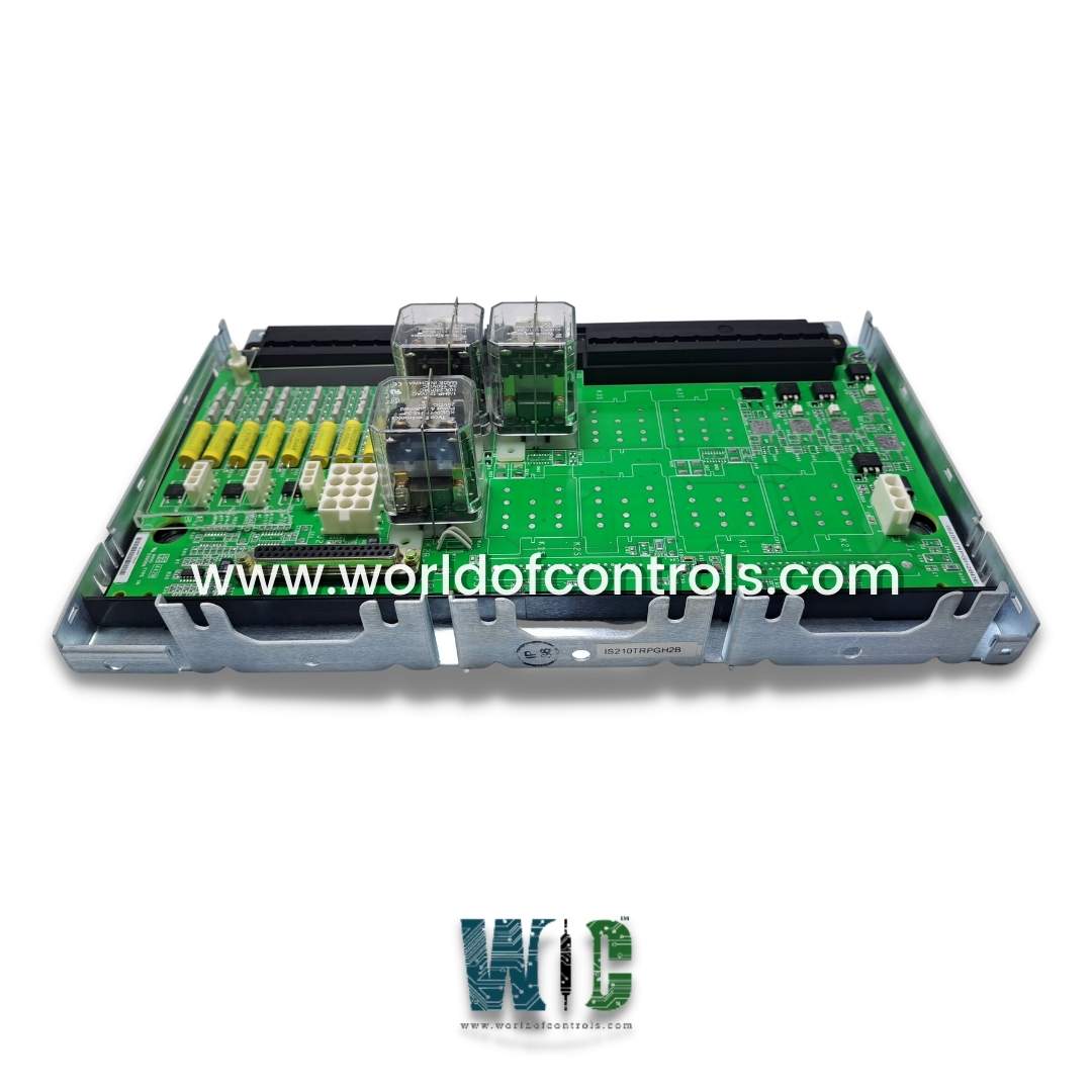
World Of Controls understands the criticality of your requirement and works towards reducing the lead time as much as possible.
IS210TRPGH3B - Gas Turbine Primary Trip Terminal Board is available in stock which ships the same day.
IS210TRPGH3B - Gas Turbine Primary Trip Terminal Board comes in UNUSED as well as REBUILT condition.
To avail our best deals for IS210TRPGH3B - Gas Turbine Primary Trip Terminal Board, contact us and we will get back to you within 24 hours.
SPECIFICATIONS:
Part No.: IS210TRPGH3B
Manufacturer: General Electric
Series: Mark VIe
Product Type: Gas Turbine Primary Trip Terminal Board
Wiring Sizes: 22 to 12
AWG Torque: 9.6 in-lb (1.085 N-m)
Trip Solenoids: 3
Flame Detectors: 8
Flame Detectors Supply Voltage: 335 V dc
Output Voltage Ripple: 280 mV pk
Maximum Output Current: 400 mA
Temperature: -30 to + 65 °C
Availability: In Stock
Country of Manufacture: United States (USA)
Manual: GEH-6721G
FUNCTIONAL DESCRIPTION:
IS210TRPGH3B is a Gas Turbine Primary Trip Terminal Board manufactured and designed by General Electric, and is part of the Mark VIe Series used in GE Distributed turbine control systems. The Gas Turbine Primary Trip (TRPG) terminal board is controlled by the Primary Turbine Protection controller (VTUR or PTUR). TRPG contains nine magnetic relays in three voting circuits to interface with three trip solenoids (ETDs). The TRPG works in conjunction with the TREG to form the primary and emergency sides of the interface to the ETDs. TRPG also accommodates inputs from eight Geiger-Mueller flame detectors for gas turbine applications. There are two board types as follows:
INSTALLATION:
Connect the wires for the three trip solenoids directly to the first I/O terminal block. Connect the wires for the flame detectors (if used) to the second terminal block. Connect the power for the flame detectors to the J3, J4, and J5 plugs. Connect the 125 V dc power for the trip solenoids to the Jl plug. Transfer power to the TREG board using the J2 plug.
OPERATION:
The I/O pack/board provides the primary trip function by controlling the relays on TRPG, which trip the main protection solenoids. In TMR applications, the three inputs are voted in hardware using a relay ladder logic two-out-of-three voting circuit. The I/O pack/board monitors the current flow in its relay driver control line to determine its energize or de-energize vote/status of the relay coil contact. Supply voltages are monitored for diagnostic purposes. A normally closed contact from each relay on TRPG is monitored by the diagnostics to determine its proper operation.
The primary overspeed trip comes from the controller and is passed to the I/O pack/board, and then to TRPG. TRPG works in conjunction with the TREG board, which is controlled by the emergency overspeed system. This TRPG/TREG combination can drive three ETDs.
FLAME DETECTORS:
The primary protection system monitors signals from eight Geiger-Mueller flame detectors. With no flame present, the detector charges up to the supply voltage. The presence of flame causes the detector to charge to a level and then discharge through TRPG. As the flame intensity increases, the discharge frequency increases. When the detector discharges, the I/O pack/board and TRPG convert the discharged energy into a voltage pulse. The pulse rate varies from 0 to 1,000 pulses/sec. These voltage pulses are fanned out to all three modules. Voltage pulses above 2.5 volts generate a logic high, and the pulse rate over a 40 ms time period is measured in a counter.
WHY PURCHASE IS210DSVOH1B FROM WOC?
WOC is a trusted global supplier known for its extensive inventory of genuine GE Distributed Turbine Control System parts, ensuring fast availability when operations are at stake. Our team of certified engineers provides quick and reliable repairs, typically completed within 3-7 days, while maintaining strict OEM-level quality standards across all components. We offer competitive pricing on new, unused, surplus, and refurbished parts, along with comprehensive warranties for added peace of mind. With worldwide shipping capabilities and 24/7 technical support, WOC delivers the expertise, reliability, and responsiveness that industries depend on to keep their systems running smoothly.
What is a Gas Turbine Primary Trip Terminal Board?
A Gas Turbine Primary Trip Terminal Board is a critical component in turbine control systems that activates the primary trip mechanism to safely shut down the turbine during abnormal conditions. It interfaces with trip solenoids and protection controllers to ensure rapid response. The board also monitors flame detectors and other inputs for reliable protection.
What is the purpose of the IS210TRPGH3B board?
The IS210TRPGH3B provides primary trip functionality for GE Mark VIe Distributed Turbine Control Systems. It controls trip solenoids and processes signals from flame detectors to trigger turbine shutdown when needed. The board works in conjunction with the TREG board for emergency trip operations. It is designed for both simplex and TMR configurations.
How many trip solenoids does this board support?
This board supports three trip solenoids, allowing it to control the main turbine protection actuators. Each solenoid is connected via relay voting circuits to ensure accurate and reliable operation. In TMR systems, the board uses hardware voting to validate the trip command. This redundancy helps prevent false trips or failures.
How many flame detectors can be connected to this board?
The IS210TRPGH3B supports up to eight Geiger-Mueller flame detectors. These detectors monitor the presence and intensity of flame in the combustion chamber. The board converts detector discharges into voltage pulses and processes the pulse rate for flame validation. This ensures accurate flame monitoring for turbine protection.