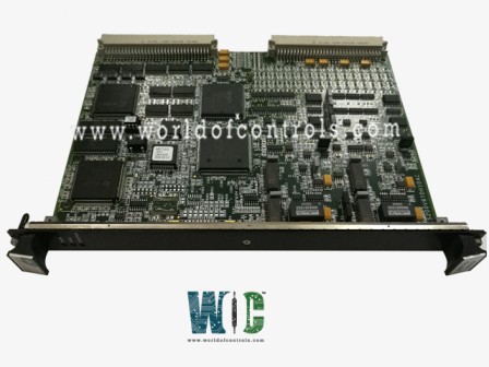
IS200VRTDH1D - Resistance Temperature Device Input Board

IS200VRTDH1D - Resistance Temperature Device Input Board IS200VRTDH1D - Resistance Temperature Device Input Board

World Of Controls understands the criticality of your requirement and works towards reducing the lead time as much as possible.

IS200VRTDH1D - Resistance Temperature Device Input Board is available in stock which ships the same day.

IS200VRTDH1D - Resistance Temperature Device Input Board comes in UNUSED as well as REBUILT condition.

To avail our best deals for IS200VRTDH1D - Resistance Temperature Device Input Board, contact us and we will get back to you within 24 hours.

SPECIFICATIONS

Part Number: IS200VRTDH1D
Manufacturer: General Electric
Series: Mark VI
Product Type: Input Board
Function: Converts the Inputs to Digital Temperature Values
Number of Channels: 16 channels per VRTD board
A/D Converter Resolution: 14-bit resolution
Power consumption: Less than 12 W
Availability: In Stock
Country of Origin: USA

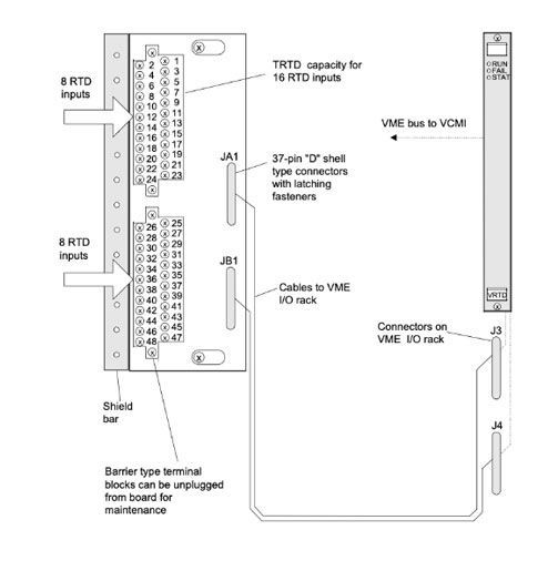
IS200VRTDH1D is a Resistance Temperature Device Input Board manufactured by General Electric as part of the Mark VI series used in gas turbine control systems. There are 16 three-wire RTD inputs on the RTD board. To an RTD terminal board, these inputs are wired (TRTD or DRTD). The terminal board is connected to the VME rack, which holds the VRTD processor board, through cables with molded fittings. RTDs are excited by the VRTD, and the ensuing signals are then returned to the VRTD. The inputs are transformed by VRTD into digital temperature values, which are subsequently sent from the VCMI to the controller through the VME backplane.
  • Turn off the processor rack for the VME.
  • Place the board in place and use your hands to press the top and bottom levers into the seat of the edge connectors.
  • Tighten the captive screws on the front panel's top and bottom.


RTD Input Terminal Board I/O Board and Cabling

 
Fig 1: RTD Input Terminal Board, I/O Board, and Cabling
IS200VRTDH1D Functional Description

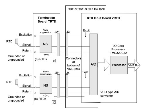
  • Through the terminal board, VRTD provides a 10 mA dc multiplexed (not continuous) excitation current to each RTD. The signal that results in returns to VRTD. Voltage to frequency converters and sample counters are used in the VCO type A/D converter. Using a temporal sample period corresponding to the power system frequency, the converter samples each signal as well as the excitation current four times per second for normal mode scanning and 25 times per second for fast mode scanning. For a choice of 15 RTD kinds, software in the digital signal processor conducts the linearization.
  • Out-of-range values are used to identify RTD short and open circuits. To avoid negative effects on other input channels, an RTD that is found to be outside the hardware limits is deleted from the scanned inputs. In 20 seconds, repaired channels are automatically restored; alternatively, they can be manually restored.
  • TRTDH1B provides redundant RTD inputs in a triple modular redundant (TMR) configuration by fanning the inputs across three VRTD boards in the R, S, and T racks. High-frequency decoupling to the ground is included at signal input for all RTD signals. Due to redundant pacemakers, RTD multiplexing ensures that no RTD signals in the control database are lost even in the event of the loss of a single cable or VRTD. RTDs are simultaneously read by the VRTD boards in R, S, and T. Each VRTD reads two RTDs different from the previous one, thus when R reads RTD3, S reads RTD5, T reads RTD7, and so on. This prevents the same RTD from being excited by two VRTDs at once and leads to inaccurate readings.


RTD Input and Signal Processing

Fig 2: RTD Input and Signal Processing
 

IS200VRTDH1D DIAGNOSTICS:

  • Information about the status is displayed by three LEDs at the top of the VRTD front panel. RUN is typically represented by a solid green and FAIL by flashing green. The third LED is generally off, but if the board has a diagnostic alert condition, it will remain steady orange. Among the diagnostic tests are the following:
  • Hardware limit checking for each RTD type is based on predetermined (non-configurable) high and low levels that are placed close to the working range's edges. The input is no longer examined once this limit is reached, and a logic signal is set instead. A composite diagnostic alarm, L3DIAG VRTD, referring to the complete board is generated whenever any input's hardware restrictions are reached. Information about each diagnosis is available from the toolbox. Individual diagnostic signals may be latched, and the RESET DIA signal may be used to reset them.

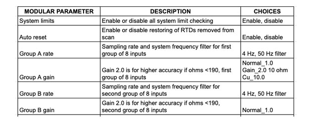
IS200VRTDH1D CONFIGURATION

IS200VRTDH1D CONFIGURATION

 
TRTDH1B and TRTDH1C work with the VRTD processor in the Mark VI system and enable simplex and TMR applications. Two cables link one TRTDH1C to the VRTD. Six connections connect TRTDH1B to three VRTD processors in TMR systems.

WOC has the largest stock of GE Speedtronic Mark VI replacement spare parts. We can repair your faulty boards. WORLD OF CONTROLS can also supply unused and rebuilt backed up with a warranty. Our team of experts is available round the clock to support your OEM needs. Our team of experts at WOC is happy to assist you with any of your automation requirements. For pricing and availability on any parts and repairs, kindly get in touch with our team by phone or email.

 
FREQUENTLY ASKED QUESTIONS


What is Mark VI IS200VRTDH1D?

It is a Resistance Temperature Device input board component used in the GE Speedtronic Mark VI control system.

What is RTD and what does it do?

An RTD is also known as Resistance Temperature Detector is a sensor whose resistance changes as its temperature changes.

How to Check Price and Availability For IS200VRTDH1D?

Please Contact World of Controls FZE for sales at +1 609 385 1231 or Request a Quote.