World Of Controls understands the criticality of your requirement and works towards reducing the lead time as much as possible.
IS200VRTDH1C - RTD Processor Board is available in stock which ships the same day.
IS200VRTDH1C - RTD Processor Board comes in UNUSED as well as REBUILT condition.
To avail our best deals for IS200VRTDH1C - RTD Processor Board, contact us and we will get back to you within 24 hours.
SPECIFICATIONS
Part Number: IS200VRTDH1C
SKU: IS200VRTDH1C
Manufacturer: General Electric
Series: Mark VI
Product Type: Processor Board
Number of Channels: 16
A/D Converter Resolution: 14-bit resolution
Availability: In Stock
Country/Region of Manufacture: United States
Repair: 3-7 Days
Manual: GEH-6421J
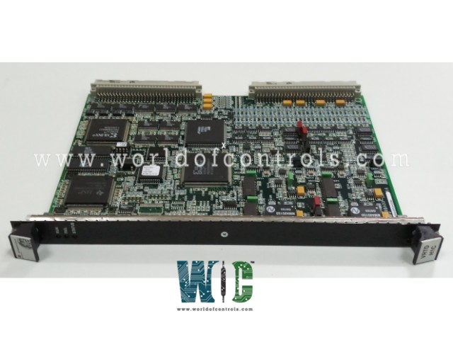
IS200VRTDH1C is an RTD Processor Board manufactured by General Electric as part of the Mark VI Series used in gas turbine control systems. There are 16 three-wire RTD inputs on the Resistance Temperature Device (RTD) processor board (VRTD). The RTD terminal board is wired to receive these inputs (TRTD). Additionally, a DRTD DIN-type terminal board may be connected. The terminal board is connected to the VME rack, which holds the VRTD processor board, through cables with molded fittings. The signals produced when the RTDs are excited by the VRTD are then returned to the VRTD. The inputs are converted to digital temperature values by the I/O processor board, which then sends those readings across the VME backplane to the VCMI and ultimately to the controller.
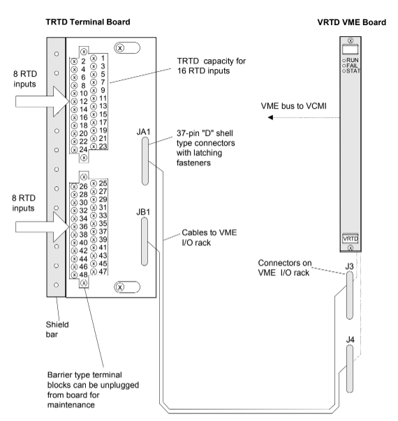
Fig 1: RTD Input Terminal Board, I/O Board, and Cabling
INSTALLATION:
OPERATION:
Each RTD is provided with a 10 mA dc multiplexed excitation current from VRTD via the terminal board (not continuously). As a result, the VRTD receives the signal. The VRTD board's VCO type A/D converter makes use of sampling counters and voltage to frequency converters. When scanning in normal mode or in fast mode, the converter samples each signal and the excitation current four times every second and 25 times every second, respectively, with a time sample interval based on the frequency of the power system. The digital signal processor utilizes software to conduct linearization for a choice of 15 RTD types.
By using out-of-range values, RTD open and short circuits are found. To avoid damaging effects on other input channels, an RTD that is found to be outside of hardware restrictions is deleted from the scanned inputs. After 20 seconds, repaired channels are automatically restored unless manually restored beforehand. Inputs from three VRTD boards in the R, S, and T racks are fanning out to give redundant RTD inputs for TRTDH1B. Although the inputs comply with the same environmental, coding, resolution, suppression, and function requirements as the TRTDH1C terminal board, the quick scan is not accessible.
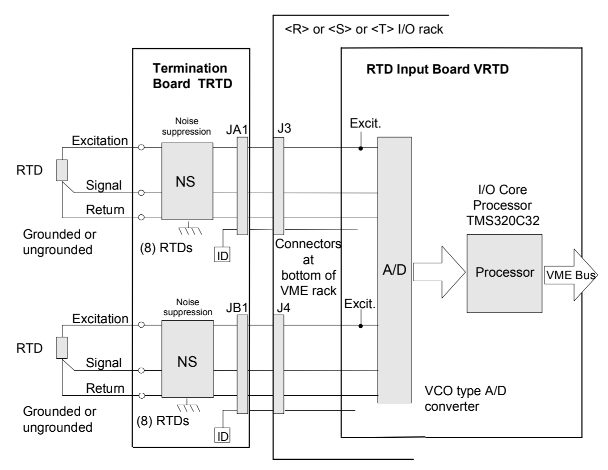
Fig 2: RTD Inputs and Signal Processing, Simplex System
High-frequency decoupling to the ground is included at signal input for all RTD signals. In order to prevent any RTD signals in the control database from being lost due to the loss of a single cable or VRTD, redundant pacemakers are used to coordinate RTD multiplexing on the VRTD boards. When R is reading RTD3, S is reading RTD5, T is reading RTD7, and so on. VRTD boards in R, S, and T read RTDs simultaneously but are skewed by two RTDs. This prevents the same RTD from being excited by two VRTDs at once and leads to inaccurate readings.
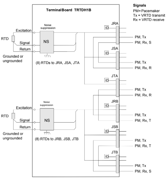
Fig 2: RTD Inputs and Connections to three VRTD Processors in TMR System
RTD TYPES AND RANGES:
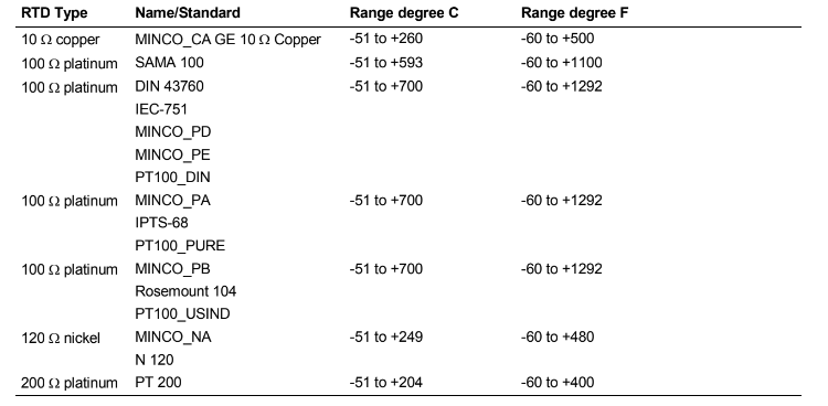
A full-scale input range of 0.3532 to 4.054 V is supported for RTD inputs. The types of RTDs that are utilized and their temperature ranges are displayed in the table below.
DIAGNOSTICS:
The VRTD front panel's three LEDs at the top display status data. Normal RUN conditions are flashing green, while FAIL conditions are solid red. When a diagnostic alert condition is present on the board, the third LED, which is typically off, turns steadily orange. Hardware limit checking and system limit checking are two diagnostic check kinds that are applied to all inputs, and they are as follows:
CONFIGURATION:
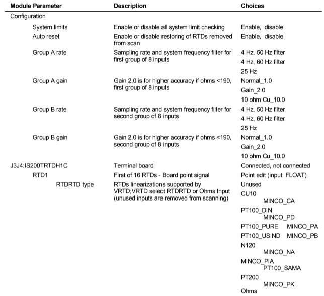
WOC has the largest stock of GE Mark VI Replacement Parts. We can also repair your faulty boards. WORLD OF CONTROLS can also supply unused and rebuilt backed up with a warranty. Our team of experts is available round the clock to support your OEM needs. Our team of experts at WOC is happy to assist you with any of your automation requirements. For pricing and availability on any parts and repairs, kindly get in touch with our team by phone or email.
What is IS200VRTDH1C?
IS200VRTDH1C is a VMR RTD Card under the GE Mark VI.
What are the LED indicators on IS200VRTDH1C?
RUN, FAIL, and STATUS are indicated by LED indicators.
How to obtain IS200VRTDH1C?
Contact WOC. World of Controls provides IS200VRTDH1C boards and other turbine control components. WOC supply worldwide.