World Of Controls understands the criticality of your requirement and works towards reducing the lead time as much as possible.
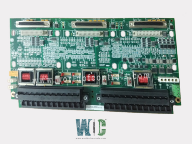
IS200TSVCH1AAA - Servo Input/Output Terminal Board is available in stock which ships the same day.
IS200TSVCH1AAA - Servo Input/Output Terminal Board comes in UNUSED as well as REBUILT condition.
To avail our best deals for IS200TSVCH1AAA - Servo Input/Output Terminal Board, contact us and we will get back to you within 24 hours.
SPECIFICATIONS:
Part Number: IS200TSVCH1AAA
Manufacturer: General Electric
Series: Mark VIe
Product Type: Servo Input/Output Terminal Board
Number of inputs: 8
Number of outputs: 2
Span: -8 mV to +45 mV
Power supply voltage: 24 V DC
Power supply current: 5 A DC
LVDT excitation output: 3.2 ±0.2 kHz
Operating temperature: 0 to +45°C
Size: 33.02 cm high x 17.8 cm
Technology: Surface Mount
Repair: 3-7 days
Availability: In Stock
Country of Origin: United States
Manual: GEH-6721G
FUNCTIONAL DESCRIPTION:
IS200TSVCH1AAA is a Servo Input/Output Terminal Board manufactured and designed by General Electric as part of the Mark VIe Series used in GE Distributed Turbine Control Systems. The Servo Input/Output (TSVC) terminal board interfaces to two electro-hydraulic servo valves that actuate the steam/fuel valves. Valve position is measured with linear variable differential transformers (LVDT). TSVC is designed specifically for the PSVO I/O pack and the WSVO servo driver, and will not work with the VSVO processor. The terminal board supports simplex, dual, and TMR control. Three 28 V DC supplies come in through plug J28. Plugs JD1 or JD2 are for an external trip from the protection module. TSVCH1 T1 through T4 isolation transformers provide galvanic isolation between the WSVO's excitation output driver and the primary side of the LVDT/R position sensor.
INSTALLATION:
Sensors and servo valves are wired directly to two I/O terminal blocks. Each block is held down with two screws and has 24 terminals accepting up to #12 AWG wiring. A shield terminal strip attached to chassis ground is located immediately to the left of each terminal block. External trip wiring is plugged into either JD1 or JD2. Each servo output can have three coils in TMR configuration. The size of each coil current is jumper-selected using JP1, 3, 5 for Servo 1, and JP2, 4, 6 for Servo 2.
OPERATION:
The TSVC servo terminal board provides two channels consisting of bi-directional servo current outputs, LVDT position feedback, LVDT excitation, and pulse rate flow inputs. It provides excitation for, and accepts inputs from, up to eight LVDT valve position inputs. There is a choice of one, two, three, or four LVDTs for each servo control loop. The two pulse rate inputs are used for gas turbine fuel flow measurement. Each servo output is equipped with an individual suicide relay under firmware control that shorts the PSVO output signal to signal common when de-energized, and recovers to nominal limits after a manual reset command is issued. Diagnostics monitor the output status of each servo voltage, current, and suicide relay.
WOC has the largest Stock of GE Distributed Control System Replacement Parts. We can also repair your faulty boards and supply unused and rebuilt boards backed up with a warranty. Our team of experts is available around the clock to support your OEM needs. Our team of experts at WOC is happy to assist you with any of your automation requirements. For pricing and availability on any parts and repairs, kindly contact our team by phone or email.
How many inputs and outputs does the board support?
The terminal board supports a total of 8 inputs from LVDT sensors, which are used to provide real-time feedback on valve positions. It also features 2 bi-directional servo current outputs, each capable of controlling a servo valve. These outputs regulate the actuator's position by adjusting the hydraulic valve mechanism based on feedback from the sensors.
What is the power supply requirement for this board?
The board operates on a 24 V DC power supply and typically draws a current of up to 5 A DC. Stable power input is essential to ensure continuous and accurate signal processing and output control. It receives power through connector J28, which supports up to three 28 V DC supplies.
What is the typical repair time at WOC?
At WOC (World of Controls), repair services typically take between 3 to 7 business days, depending on the condition and complexity of the issue. The process includes thorough diagnostics, replacement of faulty components, functional testing, and quality assurance. We use OEM-compliant practices to ensure the repaired board performs to original specifications.