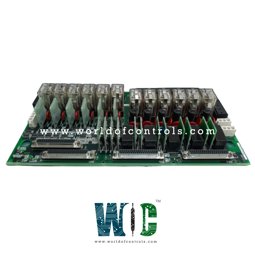
IS200TRLYS2F - Relay Output Board

IS200TRLYS2F - Relay Output Board IS200TRLYS2F - Relay Output Board

World Of Controls understands the criticality of your requirement and works towards reducing the lead time as much as possible.

IS200TRLYS2F - Relay Output Board is available in stock which ships the same day.

IS200TRLYS2F - Relay Output Board comes in UNUSED as well as REBUILT condition.

To avail our best deals for IS200TRLYS2F - Relay Output Board, contact us and we will get back to you within 24 hours.

SPECIFICATIONS

Part No.: IS200TRLYS2F
Manufacturer: General Electric
Manual: GEH-6721D
Maximum inrush current: 10A
Contact material: Silver cad-oxide
Size: 17.8 cm wide x 33.02 cm, high
Size 17.8 cm wide x 33.02 cm high
Temperature -30 to + 65oC
Availability: In Stock
Country of Manufacture: United States (USA)

Functional Description

IS200TRLYS2F is an Turbine Relay Output Board developed by GE. It is a part of Mark VIeS control system. It is a specialized interface card designed to work with a VCCC or VCRC Discrete I/O board. It operates on a voltage range of 120 VAC and 28/125 VDC, making it suitable for various industrial applications. This card is typically used in conjunction with a WPDF daughterboard, enhancing its capabilities. The relay terminal board features jumpers labeled JP1 through JP12. To enable contact voltage sensing for specific relays, users can insert jumpers as needed. This allows for customized configuration based on the relay requirements and application. Additionally, the terminal board is equipped with fuses labeled FU1 through FU12. When power is required for relays 1-6, it is essential to place two fuses in each power circuit that supplies those specific relays. For instance, FU1 and FU7 together supply power to relay output 1. Users can refer to the terminal board wiring diagram to ensure correct and precise wiring connections. Proper fuse placement ensures protection and efficient operation of the relay outputs, enhancing the overall reliability of the system.

Features

  • Solenoid Driver Relays and Dry Circuit Relays: Features 12 fused solenoid driver relays equipped with WPDF and an additional 12 dry circuit relays without WPDF. These relays are mechanical Form B type with TMR (Triple Modular Redundant) control, providing a reliable and redundant operation for critical functions.
  • Relay Suppression and Compatibility: Not backward compatible, meaning it may not work with previous versions or configurations.
  • Barrier Type Terminals and Connectors:The board is designed with barrier type terminals, ensuring secure and safe connections for various input and output signals. It features two terminal strips, each equipped with 24 terminals, providing ample space for wiring connections. Additionally, two ribbon pin male connectors are present on the right and left sides, further expanding its connectivity options.
  • RS-232 Connection Ports:On the top edge of the board, there are three RS-232 female connection ports. These ports allow for convenient communication and data exchange with other devices or systems, enhancing the board's functionality in data transmission applications.
  • Reinforced Terminal Holes and Factory Drilled Holes: Designed with two reinforced terminal holes on the two bottom corners of the board, providing additional structural integrity and durability. Additionally, there are two large factory drilled holes near the top corners, which can be utilized for mounting or securing the board in industrial setups.
  • Total Relays: It houses 36 relays, which include both solenoid driver relays and dry circuit relays. This extensive relay count showcases the board's ability to handle multiple control tasks simultaneously, making it suitable for complex and demanding applications.

Operation

  • Relay Drivers, Fuses, and Jumpers: Mounted on the relay terminal board, these components play a crucial role in controlling and protecting the relays. The relay drivers ensure precise and accurate operation of the relays, while the fuses provide essential protection against overcurrent conditions, safeguarding both the relays and connected devices. The jumpers allow users to configure the relay circuits according to specific control requirements, providing flexibility in the terminal board's functionality.
  • Frame Rate and Rating: The relays are driven at the frame rate, ensuring synchronization with other components within the control system. These relays boast a robust 3.0 A rating, enabling them to handle demanding control tasks with ease.
  • Voltage Ratings: The relay's contact-to-contact voltage is rated at 500 V AC for one minute, ensuring safe and reliable operation in high voltage applications. Additionally, the rated coil-to-contact voltage is 1,500 V AC for one minute, providing ample insulation and protection for the coil circuit.
  • Operating Time and Transient Suppression: The typical time to operate the relays is an impressive 10 ms, enabling swift and precise control actions. For added protection against voltage transients, relays 1-6 are equipped with 250 V Metal Oxide Varistors (MOVs) placed between the normally open and power return terminals. These MOVs efficiently suppress transient voltage spikes, safeguarding the relays and connected equipment from potential damage.
  • Failsafe Features: To ensure system reliability, the relay outputs are equipped with failsafe features that come into play when a cable is unplugged or communication with the associated I/O processor is lost. The inputs vote to de-energize the corresponding relays, guaranteeing a safe and controlled state in the event of communication failures.

World of Controls has the most comprehensive collection of GE Mark VIeS components. Please contact WOC as soon as possible if you require any extra information.


Frequently Asked Questions


What is IS200TRLYS2F?
It is an Turbine Relay Output Board developed by GE

What are the relay configuration options and how can contact voltage sensing be enabled for specific relays?
The relay terminal board features jumpers labeled JP1 through JP12. Users can utilize these jumpers to enable contact voltage sensing for specific relays based on their application requirements. This allows for customized configuration and precise control over the relay functions.

What is the significance of the fuses labeled FU1 through FU12 on the board?
The terminal board is equipped with fuses labeled FU1 through FU12. When power is required for relays 1-6, it is essential to place two fuses in each power circuit supplying those specific relays. For example, FU1 and FU7 together supply power to relay output 1. Proper fuse placement ensures protection and efficient operation of the relay outputs, contributing to the overall reliability of the system.

Can you explain the type of relays available and their control mechanism?
It features 12 fused solenoid driver relays equipped with WPDF, and an additional 12 dry circuit relays without WPDF. These relays are mechanical Form B type with TMR (Triple Modular Redundant) control, ensuring a reliable and redundant operation, making them well-suited for critical functions in the system.