World Of Controls understands the criticality of your requirement and works towards reducing the lead time as much as possible.
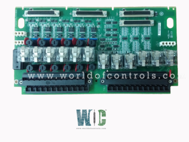
IS200TRLYH1BFD - TERMINATION BD., RELAY is available in stock which ships the same day.
IS200TRLYH1BFD - TERMINATION BD., RELAY comes in UNUSED as well as REBUILT condition.
To avail our best deals for IS200TRLYH1BFD - TERMINATION BD., RELAY, contact us and we will get back to you within 24 hours.
SPECIFICATIONS:
Part Number: IS200TRLYH1BFD
Manufacturer: General Electric
Series: Mark VIe
Product Type: Relay Output Terminal Board
Number of channels: 16
Relay Contact Rating: 10A
Input Voltage Range: 12V, 24V
Number of Relay Channels: 4, 8
Relay Switching Current: Max 10A
Mounting Type: DIN rail
Output Resolution: 12-bit
Output Impedance: 10 Ohm
Analog outputs: 0-20 mA
Size: 17.8 cm wide x 33.02 cm
Operating Temperature: -30 to 65ºC
Technology: Surface Mount
Repair: 3-7 Day
Availability: In Stock
Country of Origin: United States
Manual: GEH-6721D
FUNCTIONAL DESCRIPTION:
IS200TRLYH1BFD is a Relay Output Terminal Board manufactured and designed by General Electric as part of the Mark VIe Series used in the GE Distributed Turbine Control Systems. TRLYH1B holds 12 plug-in magnetic relays. The first six relay circuits can be jumpers configured for either dry, Form-C contact outputs, or to drive external solenoids. A standard 125 V dc or 115/230 V ac source, or an optional 24 V dc source, with individual jumper selectable fuses and onboard suppression, can be provided for field solenoid power. The next five relays (7-11) are unpowered isolated Form-C contacts. Output 12 is an isolated Form-C contact, used for special applications such as for ignition transformers. In the Mark VIe system, the PDOA I/O packs work with the TRLY board. The PDOA packs plug into the DC-37 pin connectors on the terminal board. A single PDOA on JA1 or three PDOAs on JR1, JS1, and JT1 are supported.
INSTALLATION:
The 12 relay outputs are wired directly to two I/O terminal blocks mounted on the terminal board as shown in the following figure. Each block is held down with two screws and has 24 terminals accepting up to #12 AWG wires. A shield terminal strip attached to the chassis ground is located on the left side of each terminal block. Solenoid power for outputs 1-6 is normally plugged into JF1. JF2 can be used to daisy chain power to other TRLYs. Alternatively, customer power may be wired directly into TB3 when power is not plugged into JF1/JF2. Jumpers JP1-JP6 are removed in the factory and shipped in a plastic bag. Re-install the appropriate jumper if power to a field solenoid is required. Conduct individual loop energization checks as per standard practices, and install the jumpers as required. The fuses should be removed for isolated contact applications to ensure that suppression leakage is removed from the power bus.
OPERATION:
Relay drivers, fuses, and jumpers are mounted on the relay terminal board. For simplex operation, D-type connectors carry control signals plus monitor feedback voltages between the I/O processors and TRLY through JA1. Relays are driven at the frame rate and have a 3.0 A rating. The rated contact-to-contact voltage is 500 V ac for one minute and the rated coil-to-contact voltage is 1,500 V ac for one minute. The typical time to operate is 10 ms. Relays 1-6 have a 250 V MOV for transient suppression between normally open and the power return terminals. The relay outputs have failsafe features when a cable is unplugged, or communication with the associated I/O processor is lost. The inputs vote to de-energize the corresponding relays.
WOC has the largest stock of OEM Replacement Parts for GE Distributed Turbine Control Systems. We can also repair your faulty boards and supply unused and rebuilt boards backed up with a warranty. Our team of experts is available round the clock to support your OEM needs. Our team of experts at WOC is happy to assist you with any of your automation requirements. For pricing and availability on parts and repairs, kindly contact our team by phone or email.
What is the primary function of a Relay Output Terminal Board?
The primary function of a Relay Output Terminal Board is to enable controlled switching of electrical loads while ensuring isolation between the control side and the power side. This isolation prevents electrical noise, fluctuations, or faults from affecting the control system.
What types of loads can a Relay Output Terminal Board handle?
A Relay Output Terminal Board can handle various types of electrical loads, including AC and DC-powered devices. These may include solenoids, motors, lights, heaters, pumps, and industrial actuators.
What are the typical voltage and current ratings for relay outputs?
The voltage and current ratings for relay outputs vary depending on the board design and the type of relays used. Typical voltage ratings range from low-power 12V and 24V DC applications to higher voltage AC loads of 110V or 230V.