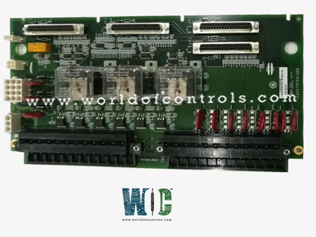
World Of Controls understands the criticality of your requirement and works towards reducing the lead time as much as possible.
IS200TRESH2A - Small Steam Turbine Emergency Trip Board is available in stock which ships the same day.
IS200TRESH2A - Small Steam Turbine Emergency Trip Board comes in UNUSED as well as REBUILT condition.
To avail our best deals for IS200TRESH2A - Small Steam Turbine Emergency Trip Board, contact us and we will get back to you within 24 hours.
SPECIFICATIONS:
Part Number: IS200TRESH2A
Manufacturer: General Electric
Series: Mark VI
Product Type: Small Steam Turbine Emergency Trip Board
Trip Solenoid Rating: 125 V DC
Trip Solenoid Circuits: Circuits rated For NEMA
Solenoid Response Time: Solenoid L/R Time constant is 0.1 sec
Thermocouple Types: E, J, K, S, T
Power supply voltage: 28 V dc
Mounting: DIN-rail mounting
Technology: Surface mount
Operating temperature: -25 to 70°C
Size: 17.8 cm wide x 33.02 cm high
Repair: 3-7 Day
Availability: In Stock
Country of Origin: United States
Manual: GEH-6721D
FUNCTIONAL DESCRIPTION:
IS200TRESH2A is a Small Steam Turbine Emergency Trip Board manufactured and designed by General Electric as part of the Mark VI Series used in GE Speedtronic Steam Turbine Control Systems. TRES is used for emergency overspeed protection for small/medium size steam turbines. TRES is controlled by the I/O controller and provides power to three emergency trip solenoids, which can be connected between the TRES and TRPS terminal boards. TRES provides the positive side of the 125 V dc to the solenoids and TRPS provides the negative side. The I/O controller provides emergency overspeed protection, and emergency stop functions, and controls the three relays on TRES, which control the three trip solenoids.
In the TRES, the seven dry contact inputs excitatio, and signal are monitored and fanned to the I/O controller. The board includes the synch check relay driver, K25A, and associated monitoring, the same as on TREG, and the servo clamp relay driver, K4CL, and its associated monitoring. A second TRES board cannot be driven from the I/O controller through J4.
INSTALLATION:
The three trip solenoids are wired to the first I/O terminal block. Up to seven trip interlocks are wired to the second terminal block. The wiring connections are shown in the following figure. Connector J2 carries three power buses from TRPS, and JH1 carries the excitation voltage for the seven-trip interlocks.
OPERATION:
The I/O controller controls TRES. In simplex systems, a third cable carries a trip signal from J1 to the TSVO terminal board, providing a servo valve clamp function upon turbine trip.
CONTROL OF TRIP SOLENOIDS:
Both TREL and TRES control the trip solenoids 1 and 2 so that either one can remove the power and actuate the hydraulics to close the steam or fuel valves. ETR3 is set up to supply power to trip solenoid #3. The nine trip relay coils on TRES are supplied with 28 V dc from the I/O controller. The trip solenoids are supplied with 125 V dc (or 24 V dc) through plug J2 and draw up to 1 A with a 0.1 second L/R time constant.
SOLENOID TRIP TESTS:
Application software in the controller is used to initiate tests of the trip solenoids. Online tests allow each of the trip solenoids to be manually tripped one at a time, either through the PTR relays from the controller, or through the ETR relays from the protection module. A contact from each solenoid circuit is wired back as a contact input to give a positive indication that the solenoid has tripped. Primary and emergency offline overspeed tests are provided too for verification of actual trips due to software-simulated trip overspeed conditions.
WOC has the largest stock of OEM Replacement Parts for GE Speedtronic Steam Turbine Control Systems. We can also repair your faulty boards and supply unused and rebuilt boards backed up with a warranty. Our team of experts is available round the clock to support your OEM needs. Our team of experts at WOC is happy to assist you with any of your automation requirements. For pricing and availability on any parts and repairs, kindly contact our team by phone or email.
What diagnostics does the I/O controller perform on the TRES board and connected devices?
The I/O controller runs diagnostics covering the trip relay driver and contact feedback, solenoid voltage, K25A relay driver and coil, servo clamp relay driver and contact feedback, and solenoid voltage source. Any deviation triggers a fault.
What information do connectors JA1, JX1, JY1, and JZ1 provide?
Each connector hosts an ID device with a read-only chip containing the terminal board serial number, board type, revision number, and plug location. This information ensures the compatibility and integrity of connected components.
What actions should be taken if a fault is detected during diagnostics or ID device interrogation?
Address faults promptly by inspecting wiring, verifying component integrity, and seeking technical support if needed. Timely resolution ensures reliable system performance.