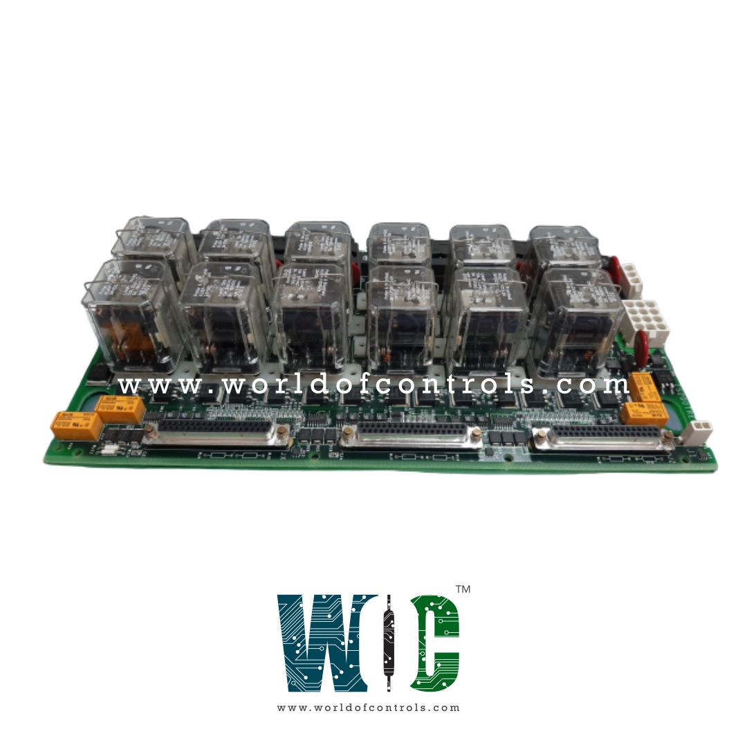
IS200TREGS2B - Turbine Protection Terminal Board

IS200TREGS2B - Turbine Protection Terminal Board IS200TREGS2B - Turbine Protection Terminal Board

World Of Controls understands the criticality of your requirement and works towards reducing the lead time as much as possible.

IS200TREGS2B - Turbine Protection Terminal Board is available in stock which ships the same day.

IS200TREGS2B - Turbine Protection Terminal Board comes in UNUSED as well as REBUILT condition.

To avail our best deals for IS200TREGS2B - Turbine Protection Terminal Board, contact us and we will get back to you within 24 hours.

SPECIFICATIONS

Part No.: IS200TREGS2B
Manufacturer: General Electric
Product Type: Turbine Protection Terminal Board
Country of Manufacture: United States (USA)
Availability: In Stock
Number of trip solenoids: 3
Size: 17.8 cm wide x 33.02 cm, high
Series: Mark VIeS

Functional Description

IS200TREGS2B is a Turbine Protection Terminal Board developed by GE. It is a part of Mark VIeS control system. The I/O pack or control board controls the Gas Turbine Emergency Trip (TREG) terminal board, which supplies power to three emergency trip solenoids (see table below). Between the TREG and TRPG terminal boards, up to three trip solenoids can be connected. TREG supplies the positive side of dc power to the solenoids, while TRPG supplies the negative side. The I/O pack, also known as the control board, provides emergency overspeed protection and emergency stop functions, as well as controlling TREG's 12 relays, nine of which form three groups of three to vote inputs controlling the three trip solenoids.

Operation

  • In the TREG system, the entirety of its operations is overseen and managed by the I/O controller, a centralized unit responsible for orchestrating all functions and processes. This controller serves as the nerve center, orchestrating the intricate interplay of components to ensure seamless operation. The control modules, essential components within the system, maintain a direct link to the I/O controller through two primary connections: the J2 power cable and via the trip solenoids.
  • In simplex systems, an additional cable serves a critical role, facilitating communication between the J1 terminal and the TSVO (Turbine Stop Valve Open) terminal board. This cable acts as a conduit for the transmission of trip signals, which play a pivotal role in the system's safety protocols. Upon receiving these signals, the TSVO terminal board activates a servo valve clamp function, swiftly and effectively halting turbine operation in the event of a trip scenario.
  • This meticulous arrangement ensures not only the efficient operation of the TREG system but also underscores its commitment to safety and reliability. By centralizing control and implementing fail-safe mechanisms such as the servo valve clamp function, the system mitigates risks and safeguards against potential disruptions, thereby upholding operational integrity and instilling confidence in its performance, even under challenging conditions.

Solenoid Trip Tests

  • The trip solenoids are tested using application software in the controller. Online tests allow each trip solenoid to be manually tripped one at a time, either through the controller's PTR relays or the protection module's ETR relays.
  • To provide a positive indication that the solenoid has tripped, a contact from each solenoid circuit is wired back as a contact input. There are also primary and emergency offline overspeed tests available for verifying actual trips due to software-simulated trip overspeed conditions.

Solenoid Response Time

  • The solenoid response time in the TREG system is crucial for ensuring efficient operation. With a solenoid L/R time constant of 0.1 second, the system boasts rapid and precise actuation, enhancing its responsiveness to control commands.

Suppression MOV Across the Solenoid

  • To further bolster the reliability of solenoid operations, a Metal Oxide Varistor (MOV) is incorporated across the solenoid. This component serves to suppress transient voltage spikes, safeguarding the solenoid and associated circuitry from potential damage.

Relay Outputs

  • Economizer Relay Outputs: The TREG system features three economizer relay outputs, each with a built-in two-second delay before energization. This delay mechanism helps optimize energy usage and ensures controlled activation of connected components.
  • Driver to Breaker Relay K25A on TTUR: A dedicated relay, K25A on TTUR, serves as the intermediary between the driver and breaker units. This relay facilitates seamless communication and coordination between these essential elements of the system, enhancing overall efficiency and reliability.
  • Servo Clamp Relay on TSVO: The TSVO (Turbine Stop Valve Open) module is equipped with a servo clamp relay, providing a critical safety feature. This relay swiftly activates the servo valve clamp function upon receiving trip signals, ensuring prompt and effective turbine shutdown in emergency scenarios.

Solenoid Control Relay Contacts

  • The solenoid control relay contacts are engineered to meet stringent performance requirements. Rated to interrupt inductive solenoid loads at 125 V DC and 1 A, these contacts exhibit robustness and reliability under demanding operating conditions.
  • Moreover, they can effectively manage variations in bus voltage, which can range from 70 to 145 V DC, ensuring consistent performance across different operating environments.

Trip Inputs

  • The system incorporates comprehensive trip inputs, comprising seven trip interlocks connected to the I/O controller protection module.
  • Operating at 125/24 V DC, these trip inputs serve as vital safety measures, monitoring critical parameters and initiating protective actions when necessary.
  • Additionally, an emergency stop hard-wired trip interlock, operating at 24 V DC, provides an additional layer of safety, enabling immediate shutdown in emergency situations.

Product Attributes

  • Number of Trip Solenoids: Equipped with three trip solenoids per TREG unit. These solenoids play a crucial role in actuating the protective trip functions of the device when required.
  • Trip Solenoid Rating: Each trip solenoid operates with a rating of 24 V DC and has an alternate current draw of 1 A. This ensures reliable and efficient operation of the solenoids during critical situations.
  • Trip Solenoid Circuits: The trip solenoid circuits are designed to meet the rigorous NEMA class E creepage and clearance standards. Additionally, these circuits have the capacity to clear a 15 A fuse when all circuits are fully loaded, further enhancing their safety and performance.
  • Solenoid Inductance: The solenoids feature a maximum L/R time constant of 0.1 second. This characteristic ensures a rapid and precise response when activating the trip solenoids, enabling effective protection of the system.
  • Suppression: Incorporates Metal-Oxide Varistors (MOV) across the solenoids. These MOVs act as voltage clamping devices, protecting the solenoids from voltage spikes and surges, and enhancing their lifespan and reliability.
  • Solenoid Control Relay Contacts: The device includes relay contacts rated to interrupt inductive solenoid loads at 125 V DC, 1 A. This capability allows to effectively control the solenoids, ensuring precise and reliable operation even in demanding conditions.
  • Bus Voltage Variability: The solenoid control relay contacts are designed to accommodate a wide range of bus voltages, varying from 70 to 145 V DC. This flexibility ensures that the device can adapt to different power system configurations and voltages.
  • Trip Interlock Isolation: All inputs for trip interlocks feature optical isolation, providing a high level of isolation up to 1500 V. This isolation ensures that the trip interlocks do not interfere with each other, enhancing the safety and reliability of the overall system.
  • Trip Interlock Filter: The device is equipped with a hardware filter for the trip interlock signals, with a filter time of 4 ms. This filter helps to stabilize and condition the interlock signals, reducing the possibility of false trips and ensuring accurate trip activation when needed.
  • Trip Interlock AC Voltage Rejection: It exhibits excellent rejection capabilities for AC voltage interference. It can reject up to 60 V RMS at 50/60 Hz at 125 V DC excitation, mitigating the impact of AC noise on the interlock signals and maintaining system integrity.

World of Controls has the most comprehensive collection of GE components. Please contact WOC as soon as possible if you require any extra information.

Frequently Asked Questions

What is IS200TREGS2B?
It is a Turbine Protection Terminal Board developed by GE.

What is the function of the I/O pack or control board?
The I/O pack or control board is responsible for controlling the TREG terminal board, providing emergency overspeed protection and emergency stop functions, and controlling TREG's 12 relays. It also manages the voting inputs controlling the three trip solenoids.

What are the power supply connections of the terminal board?
It supplies the positive side of DC power to the solenoids, while the TRPG terminal board supplies the negative side.

How many trip solenoids can be connected to the TREG and TRPG terminal boards?
Between boards, up to three trip solenoids can be connected.

What is the function of the trip signal carried by the third cable?
The third cable carries a trip signal from J1 to the TSVO terminal board in simplex systems, which provides a servo valve clamp function upon turbine trip.

What controls TREG in the control system?
It is completely managed by the PPRO / YPRO I/O pack or the VPRO board.