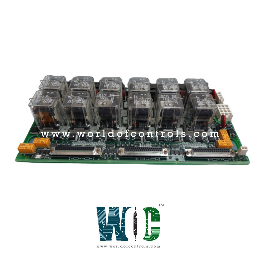
World Of Controls understands the criticality of your requirement and works towards reducing the lead time as much as possible.
IS200TREGH1AAA - Turbine Emergency Trip Terminal Board is available in stock which ships the same day.
IS200TREGH1AAA - Turbine Emergency Trip Terminal Board comes in UNUSED as well as REBUILT condition.
To avail our best deals for IS200TREGH1AAA - Turbine Emergency Trip Terminal Board, contact us and we will get back to you within 24 hours.
SPECIFICATIONS:
Part Number: IS200TREGH1AAA
Manufacturer: General Electric
Series: Mark VI
Product Type: Emergency Trip Terminal Board
Number of Trip Solenoids: 3
Relay Outputs: 3
Connectors: JX1, JY1, JZ1
Operating Voltage Range: 18–30 V DC
Operating Temperature: 0 deg C to 60 deg C
Trip Inputs: 125/24 V DC
Solenoid Response Time: 0.1 sec
Size: 17.8 cm wide x 33.02 cm
Repair: 3-7 Days
Country of Origin: USA
Availability: In Stock
Manual: GEH-6421l
FUNCTIONAL DESCRIPTION:
IS200TREGH1AAA is a Turbine Emergency Trip Terminal Board manufactured and designed by General Electric as part of the Mark VI Series used in GE Speedtronic Gas Turbine Control Systems. The TREG board supplies DC power to up to three emergency trip solenoids and is managed by the I/O controller. These solenoids are connected between the TREG and TRPG terminal boards, with TREG providing the positive DC power and TRPG supplying the return (negative) side. The I/O controller is responsible for emergency overspeed protection and emergency stop functions. It also controls 12 relays on the TREG board—nine of which are organized into three groups of three relays. These groups implement a voting logic to control the three trip solenoids. There are multiple types of TREG boards available, each designed for specific applications.
Typically, one H3B and one H4B board are used in tandem in redundant TREG applications. To preserve the control power separation built into these systems, system repairs must be carried out using the appropriate type of board.
INSTALLATION:
OPERATION:
The TREG board is fully controlled by the I/O controller. Its only connections to the control modules are via the J2 power cable and the trip solenoid circuits. In simplex systems, an additional cable from the J1 connector is used to transmit a trip signal to the TSVO terminal board. This signal activates the servo valve clamp function, ensuring the servo valves are securely held in a safe position during a turbine trip event.
CONTROL OF TRIP SOLENOIDS:
Both TRPG and TREG control the trip solenoids so that either one can remove power and actuate the hydraulics to close the steam or fuel valves. The nine trip relay coils on TREG are supplied with 28 V dc from the I/O controller. The trip solenoids are supplied with 125 V dc through plug J2, and draw up to 1 A with a 0.1-second L/R time constant.
A separately fused 125 V dc feeder is provided from the turbine control for the solenoids, which energize in the run mode and de-energize in the trip mode. Diagnostics monitor each 125 V dc feeder from the power distribution module at its point of entry on the terminal board to verify the fuse integrity and the cable connection.
Two series contacts from each emergency trip relay (ETR1, 2, 3) are connected to the positive 125 V dc feeder for each solenoid, and two series contacts from each primary trip relay (PTR1,2,3 in TRPG) are connected to the negative 125 V dc feeder for each solenoid. An economizing relay (KE1, 2, 3) is supplied for each solenoid with a normally closed contact in parallel with the current limiting resistor. These relays are used to reduce the current load after the solenoids are energized. The ETR and KE relay coils are powered from a 28 V dc source from the I/O controller. Each I/O controller in each of the R8, S8, and T8 sections supplies an independent 28 V dc source.
WOC has the largest Stock of GE Speedtronic Turbine Control System Replacement Parts. We can also repair your faulty boards and supply unused and rebuilt boards backed up with a warranty. Our team of experts is available around the clock to support your OEM needs. Our team of experts at WOC is happy to assist you with any of your automation requirements. For pricing and availability on any parts and repairs, kindly contact our team by phone or email.
How are the trip solenoids wired within the system?
Trip solenoids, economizing resistors, and the emergency stop (E-Stop) circuit are directly connected to the first I/O terminal block. This block carries the high-priority trip signal paths. Up to seven trip interlocks are connected to the second terminal block for safety and permissive conditions.
How are connectors JX1, JY1, and JZ1 identified and verified by the I/O controller?
Each connector on the TREG board has its ID device, containing essential information such as the terminal board serial number, board type, revision number, and plug location. The I/O controller interrogates these ID devices, and if a mismatch is detected, a hardware incompatibility fault is generated.
What diagnostics does the I/O controller perform on the board and connected devices?
The I/O controller conducts diagnostics covering various aspects, including trip relay driver and contact feedback, solenoid voltage, economizer relay driver and contact feedback, K25A relay driver and coil, servo clamp relay driver and contact feedback, and solenoid voltage source.