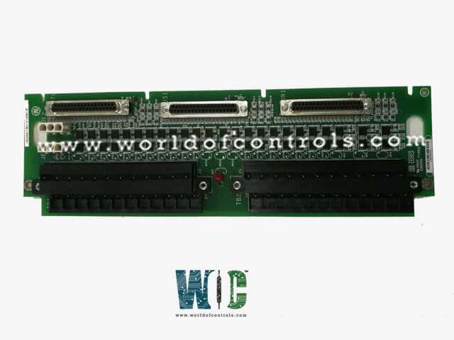
World Of Controls understands the criticality of your requirement and works towards reducing the lead time as much as possible.
IS200TBCIH2B - Contact Input Terminal Board is available in stock which ships the same day.
IS200TBCIH2B - Contact Input Terminal Board comes in UNUSED as well as REBUILT condition.
To avail our best deals for IS200TBCIH2B - Contact Input Terminal Board, contact us and we will get back to you within 24 hours.
SPECIFICATIONS:
Part Number: IS200TBCIH2B
Manufacturer: General Electric
Series: Mark VIe
Function: Contact Input Terminal Board
Size: 33.02 cm high x 10.16 cm wide
Temperature: -30 to 65 degrees Celsius
No.of channels: 24 contact voltage input channels
Input filter: Hardware filter, 4 ms
Power consumption: 20.6 W on the terminal board
Voltage: 24 VDC
Replacement Module: TBCIH2C
Connection Type: Cables or J-Port
Contact Input: 24
Size: 13.0 x W: 4.0 (in)
Voltage 24 VDC
Product type: PCB
Availability: In Stock
Country of Manufacture: United States (USA)
Manual: GEH-6721L
FUNCTIONAL DESCRIPTION:
IS200TBCIH2B is a Contact Input Terminal Board manufactured and designed by General Electric as part of the Mark VIe Series used in GE Distributed Control Systems. The terminal board Contact Input with Group Isolation accepts 24 dry contact inputs wired to two barrier-type terminal blocks. For contact excitation, it is wired with DC power. Surge and high-frequency noise are protected by noise suppression circuitry in the contact inputs. The board is compatible with the PDIA I/O pack and can handle simplex, dual, and TMR applications. This board accepts twenty-four dry contact inputs that are wired to two barrier-type terminal blocks. This board also includes noise suppression to aid in the prevention of high-frequency noise and surges. One, two, or three PDIAs can be directly connected to the module. For correct mechanical alignment of connector JT1 with I/O pack mechanical support, Mark VIe requires the C version of this board. Contact Input Terminal Board typically refers to a component used to interface and manage input signals from various sensors, switches, or contacts that monitor or control the turbine's operation. These input signals are crucial for the proper functioning and safety of the turbine. Here are some common functions of a contact input terminal board in a turbine control system:
FEATURES:
Sensor Interface: The terminal board connects to sensors such as temperature sensors, pressure sensors, flow sensors, and position sensors. These sensors provide real-time data about the turbine's condition and performance.
Switch Inputs: It can also handle inputs from various switches, including limit switches and emergency stop buttons. These switches are used for safety and control purposes.
Signal Conditioning: Some contact input terminal boards provide signal conditioning to ensure that the signals from sensors or switches are compatible with the control system's requirements.
Signal Routing: The terminal board often includes a system for routing signals to the appropriate parts of the control system, ensuring that the data is processed correctly.
Fault Detection: It may include circuitry for detecting faults or abnormalities in the input signals, which can trigger alarms or shutdown procedures to prevent damage to the turbine.
Isolation: Isolation features are sometimes included to protect the control system from electrical noise or interference that can be introduced through the input connections.
Monitoring and Diagnostics: The board may have monitoring capabilities, allowing operators to observe the status of the inputs and diagnose any issues.
WOC has the largest stock of GE Distributed Control System Replacement Parts. We can also repair your faulty boards. WORLD OF CONTROLS can also supply unused and rebuilt backed-up with a warranty. Our team of experts is available round the clock to support your OEM needs. Our team of experts at WOC is happy to assist you with any of your automation requirements. For pricing and availability on any parts and repairs, kindly get in touch with our team by phone or email.
What is a Contact Input Terminal Board?
A Contact Input Terminal Board is a hardware device used to connect external contacts, sensors, or switches to a larger electronic system. It provides a convenient way to interface these external components with electronic control systems.
How does a Contact Input Terminal Board work?
The Contact Input Terminal Board typically has screw terminals or connectors where you can attach wires from external contacts or sensors. These terminals are then connected to the input channels of an electronic control system.
What are the common applications of Contact Input Terminal Boards?
Contact Input Terminal Boards are commonly used in industrial automation, home automation, security systems, and various control applications. They can be used to monitor door/window sensors, push buttons, limit switches, and many other types of input devices