SPECIFICATIONS
Part No.: IS200TBCIH1BCD
Manufacturer: General Electric
Country of Manufacture: United States of America (USA)
Size: 15.9 cm high x 10.2 cm wide
Rating: 125 V dc nominal,
Size: 33.02 cm high x 10.16 cm wide
Input filter: Hardware filter, 4 ms
Power consumption: 20.6 watts on the terminal board
Temperature rating: 0 to 60 oC
Product Type: contact input terminal board
Availability: In Stock
Series: Mark VIe
Functional Description
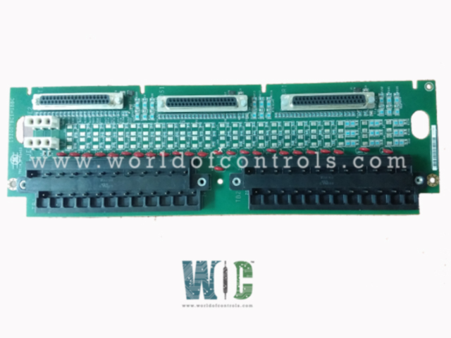
IS200TBCIH1BCD is a contact input terminal board developed by GE. It is a part of the Mark VIe control system. The Contact Input Terminal Board (TBCI) acts as a crucial bridge between external signals and the heart of the system. It accepts 24 dry contact inputs, delivered via two secure terminal blocks. A dedicated DC power supply energizes these inputs. To ensure reliable communication, the TBCI shields each input with advanced noise suppression circuitry, standing guard against harmful surges and high-frequency noise. This vigilant protection guarantees that every whisper delivered through the TBCI reaches its destination loud and clear, ensuring smooth and accurate system operation.
Features
- Handling Dry Contact Inputs: Equipped with two barrier-type terminal blocks, the component seamlessly manages 24 dry contact inputs, receiving on/off signals from external devices with enhanced safety and efficiency.
- Powering Contact Activation: A dedicated DC power supply ensures proper excitation of the contact inputs, guaranteeing their responsiveness to incoming signals.
- Shielding Against Interference: Robust noise suppression circuitry safeguards against detrimental electrical interference like surges and high-frequency noise, upholding signal integrity and reliability.
- Exploring Additional Features: Depending on the specific model, the TBCI might boast additional functionalities like fault detection mechanisms or specific operating temperature ranges.
Mark VIe System Integration
- Connecting PDIA I/O Packs: Allowing for the connection of one, two, or three PDIA I/O packs, offering flexibility based on system requirements.
- Ensuring Compatibility: For optimal alignment and secure connections with the I/O pack's mechanical support, the Mark VIe system necessitates the C version of the TBCI board.
Installation Procedure
Wiring the Dry Contact Inputs:
- Two I/O terminal blocks: These provide organized connection points for all 24 dry contact inputs. Each block can accommodate up to 12 AWG wires.
- Secure and accessible: The blocks are secured with screws but can be easily unplugged for maintenance or repairs.
- Grounding for safety: A dedicated shield terminal strip connected to chassis ground is located next to each block, ensuring proper grounding and electrical safety.
Powering:
- Excitation voltage: This powers the internal circuitry and enables it to activate the connected dry contact inputs.
- Dedicated plugs: Plugs JE1 and JE2, as shown in the provided figure, are used to connect the excitation voltage source. Ensure you follow the specified wiring diagram for accurate connections.
Cabling Connections:
- System variations: The type of connector used depends on the system configuration.
- Simplex systems: Single connector JR1 is used.
- TMR (Triple Modular Redundancy) systems: All three connectors are utilized for extra reliability and fault tolerance.
- Connection options: Depending on the specific Mark VI or Mark VIe system and its desired redundancy level, cables or I/O packs are plugged into these connectors. Refer to the relevant documentation for compatibility and configuration details.
Additional considerations:
- Wire gauges and types: Use appropriate wire gauges and types that meet the manufacturer's specifications for safe and reliable connections.
- Grounding and shielding: Ensure proper grounding and shielding practices are followed throughout the installation to prevent electrical noise and interference.
Noise Suppression and Power
- At the point of signal entry, dedicated filters tackle high-frequency noise and suppress surges on each individual input, ensuring clean and reliable signal reception. For H1 versions, the dry contact inputs operate on a floating 125 V DC supply (100-145 V DC range) sourced from the turbine control.
- This 125 V DC bus is current-limited within the power distribution module before feeding each contact input. H2 and H3 versions utilize lower voltages as specified in the relevant tables.
Signal Processing and Isolation
- Once filtered and powered, the discrete input voltage signals embark on their journey to the system controller. First, they head to the I/O processor, which acts as a central hub.
- Here, the signals are routed through optical isolators, providing critical group isolation for enhanced electrical stability. This isolation safeguards the system controller from potential ground loops and other electrical hazards.
Threshold and Clamping
- Within the isolation circuits, a dedicated reference voltage establishes a transition threshold equivalent to half of the applied floating power supply voltage. This ensures accurate signal interpretation based on voltage levels.
- However, a clever clamping mechanism steps in if the supply voltage dips below 13 percent of its nominal rate. In such scenarios, all contacts are forced to indicate an open state, preventing misinterpretations due to low voltage conditions.
- By dissecting these operational aspects, we gain a deeper understanding of the TBCI's internal workings and its vital role in accurately processing and transmitting contact input signals to the system controller.
The WOC team is always available to help you with your Mark VIe requirements. For more information, please contact WOC.
Frequently Asked Questions
What is IS200TBCIH1BCD?
It is a contact input terminal board developed by GE under the Mark VIe series.
What is the PDIA in the Mark VIe system?
PDIA stands for Process Device Interface Assembly. It is a component in the Mark VIe system responsible for interfacing with various process devices and sensors.
How many PDIA packs are supported by the TBCI, and what do they do?
One, two, or three PDIA packs can be plugged into the TBCI. These packs support a variety of system configurations, allowing for flexibility in connecting and interfacing with process devices.
Why is the C version of the board required for correct mechanical alignment?
The C version of the board is necessary for correct mechanical alignment of connector JT1 with I/O pack mechanical support. This ensures proper physical connections and prevents issues related to misalignment.
