World Of Controls understands the criticality of your requirement and works towards reducing the lead time as much as possible.
IS200JPDAG1AAA - Local AC Power Distribution Board is available in stock which ships the same day.
IS200JPDAG1AAA - Local AC Power Distribution Board comes in UNUSED as well as REBUILT condition.
To avail our best deals for IS200JPDAG1AAA - Local AC Power Distribution Board, contact us and we will get back to you within 24 hours.
SPECIFICATIONS:
Part Number: IS200JPDAG1AAA
Manufacturer: General Electric
Series: Mark VIe
Function: Local AC Power Distribution Board
Number of channels: 12 channels
Inputs: 240 V rms
Outputs: 240 V rms
Dimension: 15.875 cm high x 10.795 cm
Temperature: -35 to 65°C
Mounting: DIN-rail
Weight: 2.95 kg
Repair: 3-5 Days
Availability: In Stock
Country of Manufacture: United States (USA)
Manual: GEH-6721 L
FUNCTIONAL DESCRIPTION:
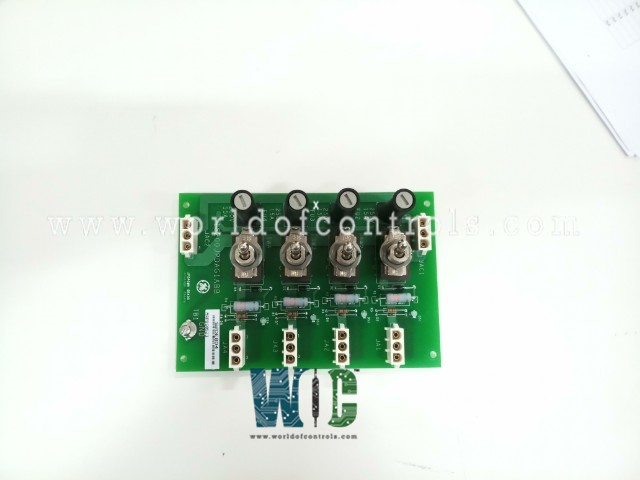
IS200JPDAG1AAA is a Local AC Power Distribution (JPDA) Board manufactured and designed by General Electric as part of the Mark VIe Series used in GE Distributed Control Systems. The JPDA board provides ac power distribution, power isolation, and branch circuit protection for each control or I/O function requiring ac power. Typical applications include ac relay and solenoid control power, ignition transformer excitation, and contact wetting. Each output includes a fuse, a switch for power isolation, and a lamp to indicate the presence of output voltage. JPDAG1A provides fuses that are coordinated with the rating of the system wiring and connectors.
INSTALLATION:
The JPDA module is designed for easy and secure mounting. It fits into a durable plastic holder that clips onto a vertical DIN rail, ensuring a stable and compact installation. The power input and output cables connect via three-position Mate-N-Lok connectors, which provide reliable and straightforward wiring. For proper cable routing and connection points, always consult the circuit diagram, which details the correct destinations for each wire.
The TB1 terminal serves as the chassis ground connection and must be connected to the system's Protective Earth (PE). This connection establishes a secure ground path for the metal switch bodies, enhancing safety and protecting the system from electrical faults or interference. Ensuring that the module is firmly mounted, connectors are properly seated, and the ground lead is correctly attached is essential for the safe, reliable, and long-term operation of the JPDA within your control system.
OPERATION:
Multiple JPDA boards receive power from a single JPDM Main Power Distribution Module. This power input is either 120 V rms or 240 V rms, 50/60Hz. Two 3-Pin Mate-N-Lok connectors are provided. One connector receives AC input power, and the other can be used to distribute ac power to another JPDA board in a daisy chain fashion. It is expected that the low or neutral side of the input power is grounded. Four output circuits are provided with three-pin Mate-N-Lok connectors. Each output circuit includes branch circuit protection and a pair of isolation contacts for the non-grounded line. There is also a green lamp to indicate the presence of voltage across the output terminals.
CONFIGURATION:
There are no jumpers on IS200JPDAG1AAA. Check the position of the four output load switches. It is possible to use other fuse ratings with this board to provide specific branch circuit ratings. A typical series of fuses that work with this board is the Bussmann ABC series of fuses with ratings from 1⁄4 A through 15A. Fuses above 15A shall not be used with this board. If alternate fuse ratings are used, the configuration of the board requires the insertion of the proper fuse in each branch circuit.
WOC offers the largest stock of GE Distributed Control System (DCS) replacement parts, including unused, rebuilt, and refurbished components, all backed by a reliable warranty. We also provide expert repair services for faulty boards and modules, ensuring your systems meet OEM standards and minimizing downtime. Our team of automation specialists is available 24/7 to assist with technical support, pricing, and availability, helping you maintain efficient and reliable control systems. Contact us by phone or email for any parts, repairs, or automation solutions you need.
What does this power distribution board do?
This Local AC Power Distribution Board supplies, isolates, and protects AC power for control and I/O components within the Mark VIe control system. It ensures that each circuit receives properly fused and isolated power. The built-in switches and indicator lamps make monitoring and maintenance simple and reliable.
How many output channels are available?
The board supports up to 12 independent AC output channels, each equipped with its own fuse and isolation switch. These channels distribute power safely to system components such as relays and solenoids. Individual fuses help prevent overloads and protect the wiring from short circuits or electrical faults.
What type of fuses can be used with this board?
It is compatible with the Bussmann ABC series fuses, rated between ¼ A and 15 A. The correct fuse rating should be selected based on the load requirements of each branch circuit. Fuses rated above 15 A should not be used to ensure system safety and prevent equipment damage.
What is the typical repair or replacement time?
Repairs are typically completed within 3 to 5 business days, depending on component availability and the extent of service required. Each repaired board is tested to meet OEM performance standards. This fast turnaround helps minimize downtime in industrial operations.