World Of Controls understands the criticality of your requirement and works towards reducing the lead time as much as possible.
IS200ECTBG2A - Exciter Contact Terminal Board is available in stock which ships the same day.
IS200ECTBG2A - Exciter Contact Terminal Board comes in UNUSED as well as REBUILT condition.
To avail our best deals for IS200ECTBG2A - Exciter Contact Terminal Board, contact us and we will get back to you within 24 hours.
SPECIFICATIONS:
Part Number: IS200ECTBG2A
Manufacturer: General Electric
Series: EX2100
Relay Break Characteristic: 28 V dc
Operational Mode: Simplex mode only
Customer Power: 125 V dc
Function: Exciter Contact Terminal Board
Relay Control Voltage: 24 V DC
Wetting Voltage: 70 V DC
Weight: 0.34 kg
Dimensions: 150 x 76 x 90 mm
Availability: In Stock
Country/Region of Manufacture: United States
Manual: GEI-100457A
FUNCTIONAL DESCRIPTION:
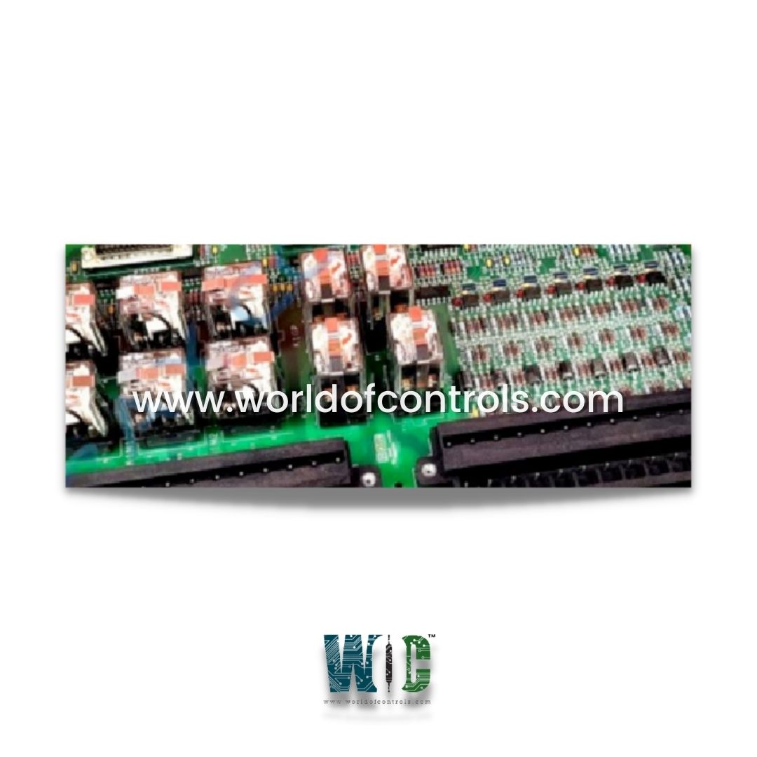
IS200ECTBG2A is an Exciter Contact Terminal Board manufactured by General Electric as part of the EX2100 series used in the Excitation control system. The ECTB board supports excitation contact outputs and contact inputs. The ECTBG2 board is only used in the simplex mode. Each board contains two trip contact outputs driving a customer lockout, and four general-purpose Form-C relay contact outputs, controlled by the EMIO board. Six auxiliary contact inputs are powered (wetted) with 70 V dc by ECTB. Also, the 52G and 86 G contact inputs are powered and monitored by ECTB. In the redundant case, power comes from the M1 and M2 power supplies. There are also four general-purpose Form-C contact outputs controlled by the EMIO board. Six auxiliary contact inputs are powered (wetted) with 70 V dc and monitored by ECTB. Also, the 52G and 86 G contact inputs are powered with 70 V dc and monitored. In the redundant control, power comes from both the M1 and M2 controllers.
RELAY CONTROL AND FEEDBACK:
Trip Relay Outputs (Simplex/Redundant):
ECTBG2, driven by the EMIO in M1, controls two trip relays normally used as customer lockout drivers. The relay drivers are powered by 24 V dc from the M1 controller. Refer to the previous figure ECTBG2 Terminal Board, Simplex. Each customer lockout is driven by one relay using two parallel normally closed contacts. On the board, the relays are designated K1M1 and K2M1. For redundant control operation with ECTBG1, the three inputs drive three relays that control a 2- out of 3 contact voting circuit.
GENERAL PURPOSE RELAY OUTPUTS (Simplex/Redundant):
ECTBG2 controls four general-purpose relay outputs. The relay drivers are powered by 24 V dc from the M1 controller. Each relay output is a Form-C type with normally open, normally closed, and common terminals. Customer power, nominally 125 V dc, is wired to these terminals. On the board, the relays are designated K1GP, K2GP, K3GP, and K4GP. For redundant operation with ECTBG1, the three inputs are voted in the relay driver, which drives the single coil.
CONTACT INPUTS:
Contact input uses are similar in the simplex and redundant cases, however, the inputs are fanned to the M1, M2, and C controllers for redundant control. In simplex control, only the M1 controller is connected. Six customer-supplied auxiliary contact inputs are powered and monitored by ECTB using 70 V dc from plugs J13M1 and J13M2 are resistor-isolated and supplied to the contacts. The wetting voltage can vary from 63 to 84 V dc. The state of the contact is monitored. The resulting signal drives a red indicating LED, and fans out to M1, M2, and C. One contact from 52G is monitored using the 70 V dc excitation in the same way as the auxiliary inputs. The status is indicated with a red LED. One contact from 86G is wetted with a nominal 70 V dc as above. The state of the contact is monitored by controllers M1, M2, and C.
APPLICATION DATA:
K1 and K2 are the trip relays in controllers M1, M2, and C. K1GP through K4GP are the general-purpose relays. Terminal blocks TB1 and TB2 are held down with two screws and can be removed. Three 25-pin sub-D connectors, J405, J408, and J415 are for cables to the EBKP backplane for connection to the EMIO boards M1, M2, and C. Plugs J13M1 and J13M2 bring in 70 V dc for contact wetting from the M1 and M2 power supplies.
WOC has the largest stock of GE Speedtronic Gas turbine control systems replacement parts. We can also repair your faulty boards and supply unused and rebuilt boards backed up with a warranty. Our team of experts is available round the clock to support your OEM needs. Our team of experts at WOC is happy to assist you with any of your automation requirements. For pricing and availability on any parts and repairs, kindly contact our team by phone or email.
What are the common features of exciter contact terminal boards?
Exciter contact terminal boards may include features such as labeled terminals for easy identification of connections, protective covers or enclosures to prevent accidental contact and mounting provisions for secure installation within the electrical system.
What are the different types of exciter contact terminal boards available?
Exciter contact terminal boards come in various configurations to suit different types and sizes of generators and motors. They may vary in terms of the number of terminals, terminal sizes, voltage and current ratings, and mounting options.
How do I select the right exciter contact terminal board for my application?
When selecting an exciter contact terminal board, consider factors such as the voltage and current requirements of your generator or motor, the type of excitation system used, available space for installation, and any specific mounting or connectivity requirements.