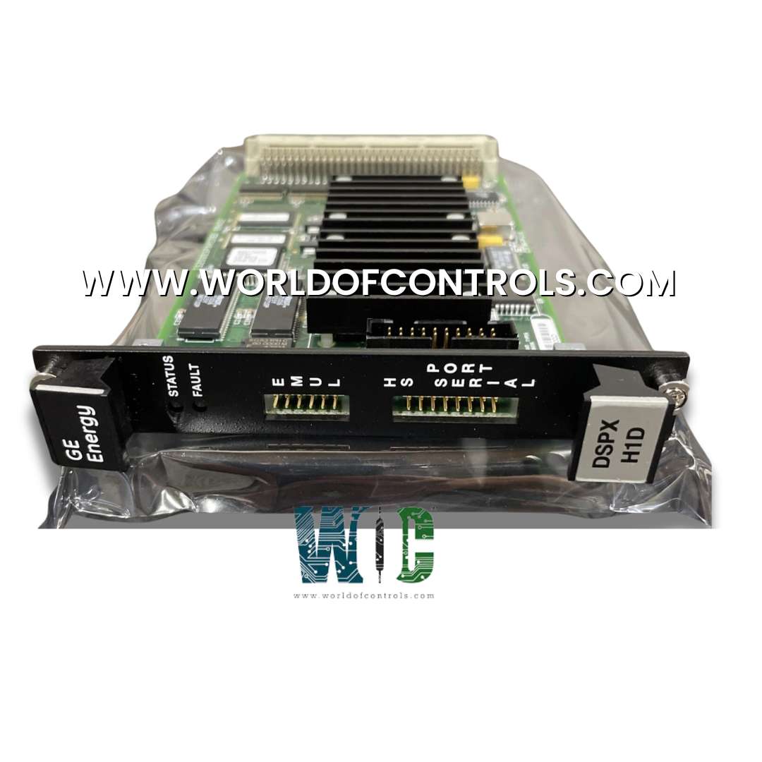
IS200DSPX2B - Drive Digital Signal Processor Control Board

IS200DSPX2B - Drive Digital Signal Processor Control Board IS200DSPX2B - Drive Digital Signal Processor Control Board

World Of Controls understands the criticality of your requirement and works towards reducing the lead time as much as possible.

IS200DSPX2B - Drive Digital Signal Processor Control Board is available in stock which ships the same day.

IS200DSPX2B - Drive Digital Signal Processor Control Board comes in UNUSED as well as REBUILT condition.

To avail our best deals for IS200DSPX2B - Drive Digital Signal Processor Control Board, contact us and we will get back to you within 24 hours.

SPECIFICATIONS:

Part Number: IS200DSPX2B
Manufacturer: General Electric
Product Type: Drive Digital Signal Processor Control Board
Series: Mark VIe
Number of outputs: 2
Power supply voltage Nominal: 28 V DC
Pulse rate accuracy: 0.05%
Magnetic PR pickup signal generates: 150 V
Operating temperature: -30 to +65°C
Size: 8.26 cm high x 4.19 cm
Input Filter: Hardware Filter, 4 ms
Technology: Surface-mount
Availability: In Stock
Weight: 0.8kg
Repair: 3-7 days
Country of Origin: USA
Manual: GEH-6721D

FUNCTIONAL DESCRIPTION:

IS200DSPX2B is a Drive Digital Signal Processor Control Board manufactured and designed by General Electric as part of the Mark VIe Series used in GE Distributed Turbine Control Systems. The IS200DSPX Digital Signal Processor Control Board (DSPX) is the primary controller for the bridge and motor regulator and gating functions for Innovation Seriesä drives. It also controls generator field control functions for the EX2100 Excitation Control. The board provides logic, processing, and interface functions. The DSPX board includes a high-performance digital signal processor (DSP), standard memory components, and an application-specific integrated circuit (ASIC) that performs custom logic functions.

STANDARD HARDWARE FEATURES:

The DSPX board features a Digital Signal Processor (DSP) operating at 60 MHz. During normal operation, the DSP utilizes four external interrupts:

  • INT0: Stack Overflow
  • INT1: Inner Loop Load Pulse
  • INT2 & INT3: Two user-configurable inputs

THE DSPX BOARD INCLUDES THE FOLLOWING MEMORY TYPES:

  • FLASH Memory: Used for DSP boot images, code execution, configuration storage, and system history logs.
  • RAM: Supports data storage and code execution.
  • NVRAM: Provides nonvolatile data storage.
  • Add-Only Memory: Contains board revision identification.

SPECIALIZED HARDWARE FUNCTIONS:

The DSPX board utilizes custom logic implemented in Field Programmable Gate Arrays (FPGAs) or ASICs, along with necessary support circuitry, to perform its specialized functions. Most of these functions are integrated within a single ASIC.

  • The board provides four serial interfaces via connector P1:
  • Two 5 Mb/s ISBus interfaces, configurable as either master or slave
  • One asynchronous TTL interface for a PC-based configuration tool, supporting RX, TX, and TXEN/RTS signals
  • One asynchronous TTL interface for connection to a programmer board, supporting RX, TX, and RTS signals

SYNCHRONIZING LOAD PULSE SIGNALS:

  • Inner Loop Load Pulse: Captures I/O values such as voltages and currents from bridges, motors, or generators, as well as VCOs, tachometer counters, and discrete inputs. It also synchronizes ISBus channels, software functions, and gating outputs to the bridges.
  • Application Loop Load Pulse: Operates at a multiple or sub-multiple of the inner loop pulse to capture values from application-specific VCOs and, optionally, tachometers.
  • The DSPX board provides stack overflow detection for both the foreground stack (stored in internal memory) and the background stack (located in external SRAM). If either stack overflows, the interrupt INT0 is triggered. In the event of both stacks overflowing simultaneously, the board initiates a hard reset.
  • The board also features a watchdog timer, which the DSP periodically toggles. The toggle interval is configurable. If the DSP fails to toggle the timer within the specified interval, a hard reset is triggered. Additionally, a 24-bit free-running timer is included to serve as a time reference for various operations.

DIFFERENTIAL HIFI INPUT FUNCTIONS:

  • The board supports five differential (HIFI) pair application inputs, which may be used as two quadrature incremental tachometer interfaces (one supporting marker capability). These inputs drive two 16-bit up/down counters. The counters remain stable when both input levels are equal and increment or decrement when the inputs are differentially opposite.
  • A 5 MHz timer resets with every count change, and a state register tracks the last count direction. Each counter and its associated timer and state register have a capture register that can be configured to store values on either the inner loop load pulse or the application loop load pulse.
  • These five HIFI inputs can also function as application-level VCO counters or single-channel tachometer interfaces. Each is linked to a 16-bit counter that increments on differentially decoded and filtered signals. The current counter values are captured by the application loop load pulse and read by the DSP.
  • Alternatively, the five differential HIFI inputs can serve as up to ten discrete inputs. Each input is filtered over three system clock cycles and is directly accessible by the DSP via a buffer.

WOC has the largest stock of GE Distributed Control System Replacement Parts. We can also supply unused and rebuilt backup with a warranty. Our team of experts is available around the clock to support your OEM needs. Our team of experts at WOC is happy to assist you with any of your automation requirements. For pricing and availability on any parts and repairs, kindly get in touch with our team by phone or email.

FREQUENTLY ASKED QUESTIONS:

What processor is used in the DSPX board?

The DSPX board incorporates a 60 MHz fixed-point Digital Signal Processor (DSP), optimized for deterministic real-time control applications, enabling high-speed signal acquisition, filtering, and control loop execution.

How does the board handle stack overflows?

The DSPX monitors both the internal (foreground) and external SRAM (background) stacks. If either overflows, interrupt INT0 is raised; simultaneous overflow on both stacks results in an immediate hardware-initiated reset.

What serial communication interfaces are available?

DSPX supports two high-speed ISBus interfaces at 5 Mbps (configurable as master/slave), one TTL UART port for PC configuration (with TX, RX, TXEN/RTS), and a second TTL UART for firmware programming interfaces.