SPECIFICATIONS
Part Number: IS200CVMBG1A
Manufacturer: General Electric
Series: Drive Control
Assembly Level: Base
Functional Acronym: CVMB
Manual: GEI-100415
Mounting Location: DC Power Capacitor Terminals (Directly)
Neon Lamps: 3 - DS1, DS2, and DS3
Power Dissipated: 3 - 5 W Power
Function: Capacitor voltage monitoring board
Availability: In Stock
Product Type: Board
Country of Manufacture: United States (USA)
Functional Description
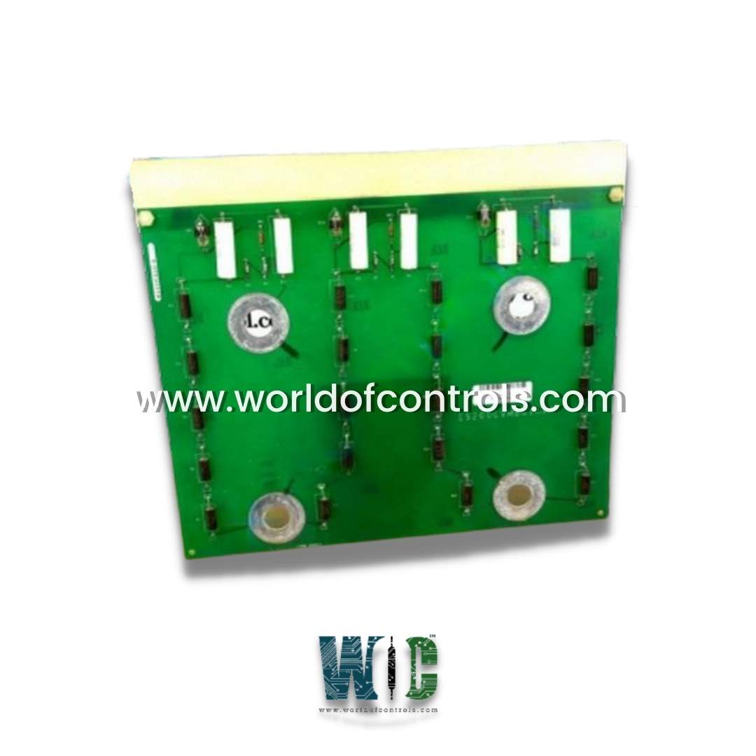
IS200CVMBG1A is a capacitor voltage monitoring board developed by General Electrics. It is a part of GE drive control system. It is used to monitor voltages in Innovation Series Drives. This board is responsible for voltage monitoring across DC link capacitors. Furthermore, three neon lamps on the board blink when high voltage is present on the DC bus to warn users when the bridge cabinet doors open. These lamps are clearly visible.
Features
- It is a component used in Innovation Series drives to monitor voltage across DC link capacitors.
- When the bridge cabinet doors are opened, the card provides turbine operators with a secondary indication of the presence of voltage. This board includes three (3) small neon lamps labeled DS3, DS2, and DS1. These are located along the top edge in a horizontal line. When the bridge cabinet's doors are opened, they are clearly visible.
- When the DC bus contains a high voltage of more than fifty (50) volts DC, these small lamps blink. An attenuator network controls these neon lamps.
- Both bulb clips and bulbs can be replaced with the 68A944080P1 and 68A7804P4 parts. It has no test points, fuses, connectors, or adjustable hardware. With four through-plate mounting holes labeled E1, E2, E3, and E4, this board can be mounted directly onto the DC power capacitor's terminals. E2 and E1 are located on the left half of the printed circuit board, while E3 and E4 are located on the right half of the PCB. It requires no input power and dissipates between three and five watts of power.
- Within the drive system, DC link capacitors play a vital role in stabilizing and smoothing the direct current (DC) voltage supplied to the drive's components. These capacitors act as energy reservoirs, storing electrical energy and supplying it as needed, helping to maintain a stable and continuous power supply to the drive. However, to ensure optimal performance and safety, it is crucial to monitor the voltage levels across these capacitors.
- The CVMB is specifically designed to monitor the voltage across each DC link capacitor continuously. By doing so, it can detect any deviations or irregularities in the voltage levels, allowing the drive system to respond quickly to potential issues. This voltage monitoring capability helps prevent voltage fluctuations that could lead to operational problems or damage to the drive components.
- Furthermore, the CVMB is equipped with three neon lamps, which serve as visual indicators to warn users of high voltage on the DC bus. When high voltage is detected on the DC bus, these neon lamps start blinking, providing a clear and immediate visual signal. The blinking neon lamps are strategically placed to be visible from the bridge cabinet doors.
- The blinking neon lamps serve as a crucial safety feature, alerting users or maintenance personnel to the presence of high voltage when the bridge cabinet doors are open. This warning system helps prevent accidental exposure to high voltage, ensuring the safety of those working on the drive system.
Product Attributes
- Its main function is to monitor the voltage across the capacitors in the drive's power module. The board includes a number of voltage sensing circuits that measure the voltage across each capacitor and provide this information to the drive's control system.
- In addition to monitoring the capacitor voltages, the board also includes protection circuitry that is designed to prevent overvoltage conditions. If an overvoltage condition is detected, the board will immediately signal the drive to shut down to prevent damage to the capacitors or other components.
- The board is typically installed inside the drive's power module and is connected to the drive's control system through a set of input/output connectors. Its compact size and robust design make it well-suited for use in demanding industrial applications.
Mounting and Connections
The installation of the IS200CVMBG1AAA board is facilitated through plated mounting holes, which are conveniently identified with the labels E1 through E4. When connecting the board, specific connections are required:
- E4: DC link negative connection
- E3: NEU2 at 2000 VDC, relative to the negative indicated by DS2
- E2: NEU2 at 2000 VDC, relative to the negative indicated by DS1
- E1: POS nomenclature at 4000 VDC, relative to the negative indicated by DS3
Identification
- To easily identify this model, look for the alphanumeric catalog number. This catalog number follows a specific convention, as detailed in the GEI-100415 Manual. For instance, it signifies that CVMB is the functional acronym, withG representing the group variation of the model.
- Understanding this convention aids in accurate model recognition and usage within the system.
WOC has the largest stock of Speedtronic control spares. Please contact our staff by phone or email for pricing and availability on any parts and repairs
FREQUENTLY ASKED QUESTIONS
What is IS200CVMBG1A?
It is a capacitor voltage monitoring board developed by General Electrics.
Does the board require input power?
No, the board requires no input power.
How much power does the board dissipate?
The board dissipates between three and five watts of power.
