World Of Controls understands the criticality of your requirement and works towards reducing the lead time as much as possible.
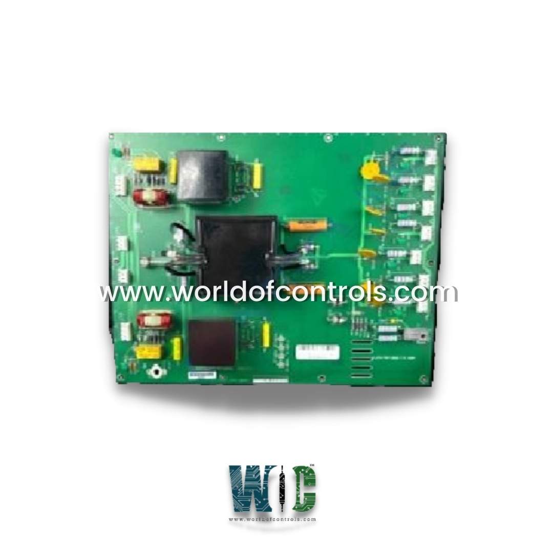
IS200CPFPG1A - Control Power Flash Protect Board is available in stock which ships the same day.
IS200CPFPG1A - Control Power Flash Protect Board comes in UNUSED as well as REBUILT condition.
To avail our best deals for IS200CPFPG1A - Control Power Flash Protect Board, contact us and we will get back to you within 24 hours.
SPECIFICATIONS:
Part Number: IS200CPFPG1A
Manufacturer: General Electric
Series: Drive Control
Product Type: Control Power Flash Protect Board
Addressing Range: 16 and 32 bits
Common Mode Voltage Range: ±5 V
Fuses: FU1, FU2, FU3
Jack connector ports: 11
Dimensions: 11.00 x 9.00 x 3.00
Operating temperature: 0 to 60 °C
Storage Temperature: -40 to 80 °C
Repair: 3-7 days
Availability: In Stock
Country of Origin: United States
Manual: GEH-6385
FUNCTIONAL DESCRIPTION:
IS200CPFPG1A is a Control Power Flash Protect Board manufactured and designed by General Electric as part of the Drive Control Innovation Series used in GE Speedtronic Innovation Turbine Control Systems. The CPFP isolation lost trip fault is hardware-generated. The CPFP power supply isolation card indicates that power supply isolation to the phase modules has been compromised. The CPFP card is designed to provide control power to circuit cards in the high-voltage compartment. This card has a double voltage barrier that isolates the phases from each other and the control. This fault indicates that one of these voltage barriers has failed. This is a dangerous situation since failure of the second barrier could cause dangerous voltages to conduct into the control cabinet or cause a phase-phase short on the CPFP card. The fault is generated when the status light conducted via fiber from the CPFP goes out. The fiber connects CPFP (PWR OK) to FOSA (SPARE-R). Check that the fiber is installed correctly. Disconnect the fiber from FOSA and look for the status light traveling up the fiber. If you do not see a light, then the problem is on the CPFP. If there is light, then the problem is on FOSA or BICM.
INSTALLATION:
The installation process for the Control Power Flash Protect Board is a critical step to ensure its effectiveness in safeguarding sensitive control circuits. Before beginning, it is essential to disconnect all power sources to prevent electrical hazards or accidental damage. The board should be mounted in a secure location, ideally close to the power input of the device it is protecting. Using insulated screws or standoffs is recommended to avoid any risk of short circuits.
When connecting the wiring, the input power lines—whether AC (L/N) or DC (+/-)—must be attached to the appropriate terminals on the board. The output lines should then be connected to the control circuit that requires protection. Proper grounding is crucial, so the board’s ground terminal must be linked to a reliable earth ground to ensure optimal performance. Before powering up the system, it is important to double-check the polarity and confirm that the input voltage matches the board’s specifications to avoid potential damage.
OPERATION:
The Control Power Flash Protect Board operates automatically to detect and mitigate power anomalies, ensuring the stability and safety of the connected control circuit. Under normal conditions, when the power supply is stable and within the specified range, the board allows uninterrupted power flow to the protected device. Many boards feature status indicators, such as LED lights, to signal normal operation, typically displayed as a solid green light.
In the event of a voltage surge or transient spike, the board’s protective mechanisms activate immediately. Components such as Metal Oxide Varistors (MOVs) or transient voltage suppression (TVS) diodes absorb excess voltage, diverting harmful energy away from the control circuit. If the voltage exceeds a safe threshold, the board may temporarily cut off power to prevent damage. Some advanced models include self-resetting fuses or circuit breakers that restore power once conditions normalize.
WOC has the largest stock of OEM replacement parts for GE Drive Control Turbine Control Systems. We can also repair your faulty boards and supply unused and rebuilt boards backed up with a warranty. Our team of experts is available around the clock to support your OEM needs. Our team of experts at WOC is happy to assist you with any of your automation requirements. For pricing and availability on any parts and repairs, kindly contact our team by phone or email.
What is a Control Power Flash Protect Board?
The Control Power Flash Protect Board is an essential component designed to protect sensitive control circuits from electrical disturbances such as voltage spikes, surges, and flashovers. These disturbances can occur due to lightning strikes, switching operations, or faults in the power system, potentially damaging relays, PLCs, and other electronic devices.
How do response time specifications impact protection effectiveness?
The response time specification, typically measured in nanoseconds, directly determines how quickly the protection circuitry reacts to transient events. For sensitive semiconductor devices like MOSFETs or IGBTs in modern control circuits, a response time under 1 nanosecond is critical to prevent damage from fast-rising transients.
What are typical voltage ratings?
Control Power Flash Protect Boards are available in various voltage ratings to match different systems, including 24V DC (for PLCs and sensors), 120V/240V AC (for industrial control circuits), and 480V AC (for high-power applications).