World Of Controls understands the criticality of your requirement and works towards reducing the lead time as much as possible.
IS200BPIBG1A - Phase Logic Interface Module is available in stock which ships the same day.
IS200BPIBG1A - Phase Logic Interface Module comes in UNUSED as well as REBUILT condition.
To avail our best deals for IS200BPIBG1A - Phase Logic Interface Module, contact us and we will get back to you within 24 hours.
SPECIFICATIONS:
Part No.: IS200BPIBG1A
Manufacturer: General Electric
Function: Phase Logic Interface Module
Series: EX2100
Memory: Serial 1024-bit chip
Input channel: 40
Operating Voltage: 24 VDC
Output Current: 0.5 A to 2 A
Dimensions: 11.00 x 9.00 x 3.00
Isolation Voltage: 2500 V
Mounting: DIN Rail
Response Time: < 10 ms
Voltage Feedback VCO Range: 0-20 MHz
Power: 17.7 VAC or 5 VDC
Operating Temperature: -20°C to +70°C
Availability: In Stock
Country of Manufacture: United States (USA)
FUNCTIONAL DESCRIPTION:
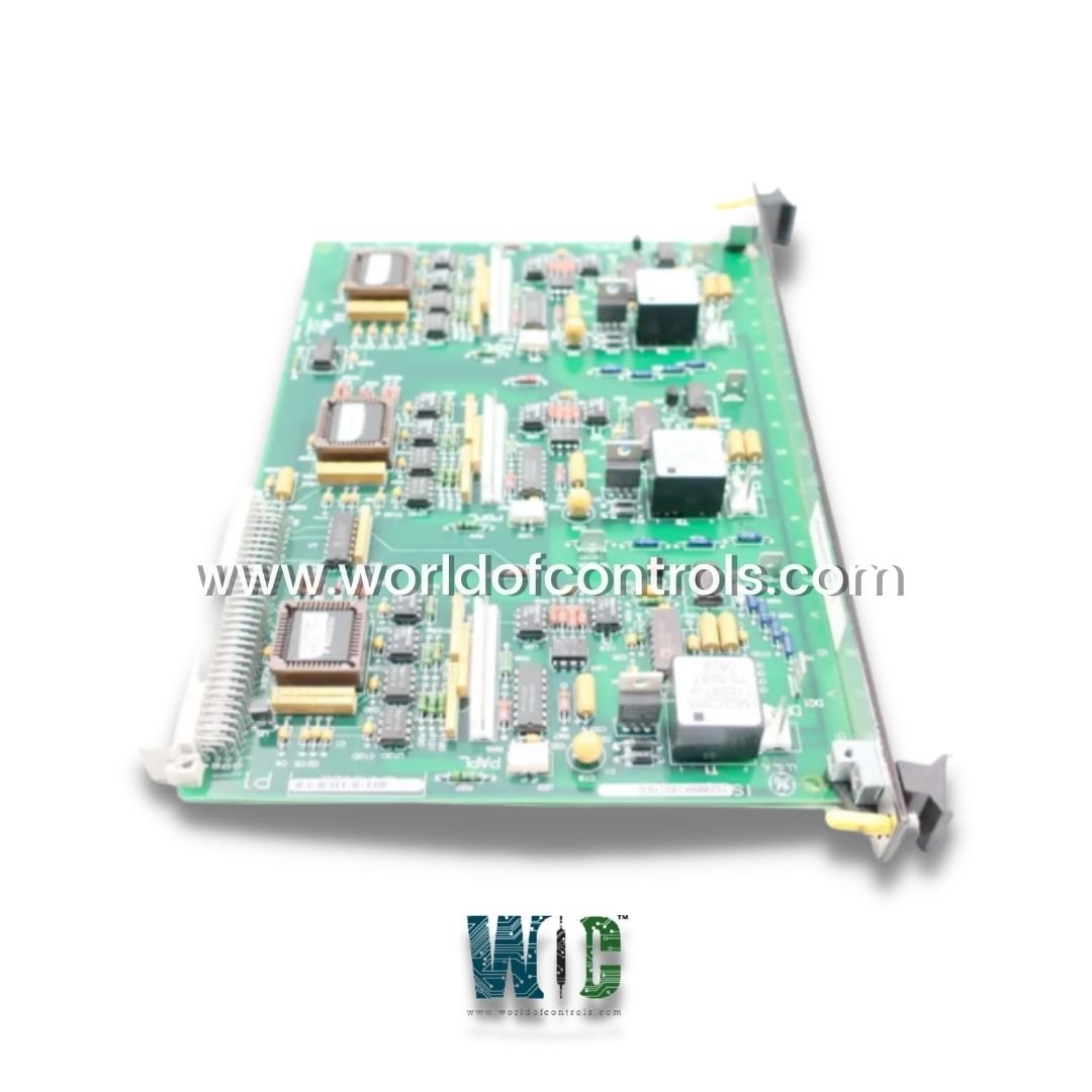
IS200BPIBG1A is a Phase Logic Interface Module manufactured and designed by General Electric as part of the EX2100 Series used in GE Excitation Control Systems. It is a Phase Logic Module/ IGBT Drive Personality Interface board. The module captures and reports faults in conjunction with an associated and connected Gate Driver board or boards. Some of these faults are handled on the BPIB board. The PCB is also used for signal conditioning to the Gate Driver and Shunt Feedback boards via its P1 connector (located on its rear edge). The board is intended to be plugged into a VME rack.
This is accomplished through the P1 connector, located on the board's back edge. Six plug connectors connect the board to several IGBT boards. Five stab-on connectors are used to detect Phase A/B/C sensing signals as well as DC-link positive and negative signals. Internally, the PLIM utilizes opto-isolation and galvanic separation to ensure high noise immunity and signal integrity. It supports configurable logic levels (e.g., 24 VDC, 48 VDC, or 125 VDC) and can accommodate sinking or sourcing input/output configurations depending on control scheme requirements. Fault diagnostics, signal forcing, and handshake protocols are typically integrated via firmware or control software.
INSTALLATION (MOUNTING AND ENVIRONMENT):
The PLIM is installed within a protected control cabinet—often in the turbine control enclosure or auxiliary panel. It should be DIN-rail mounted or rack-mounted, depending on the module form factor. Ambient environmental conditions must conform to the manufacturer's operating specifications, typically:
The module must be installed away from sources of electromagnetic interference (EMI) and must comply with grounding and shielding practices outlined in IEEE Std. 518 or IEC 61000.
OPERATION:
The PLIM functions as a real-time conduit for executing phase-based control sequences. The phase logic executed in the main controller issues commands that are processed by the PLIM as high-speed logic-level transitions (type response time <10 ms). The PLIM executes the following key functions:
OUTPUT CONTROL:
Digital output signals (DO) are latched and energized by the PLIM according to phase interlocks and permissives. Each output channel is:
The outputs are often interlocked using hardware- or software-based voting logic (e.g., 2-out-of-3) to ensure safety-critical commands (e.g., trip signal to fuel shut-off valve) are executed with integrity.
INPUT MONITORING:
Digital input signals (DI) are scanned continuously to detect state changes. These include position feedback, trip conditions, and permissive confirmations. Edge detection logic in the PLIM may be configured to debounce mechanical contact chatter and filter transient signals. Input conditions are time-correlated with logic solvers to form a closed-loop response system. For instance:
WOC has the largest stock of OEM Replacement Parts for GE Excitation Control systems. We can also repair your faulty boards and supply unused and rebuilt boards backed up with a warranty. Our team of experts is available around the clock to support your OEM needs. Our team of experts at WOC is happy to assist you with any of your automation requirements. For pricing and availability on any parts and repairs, kindly contact our team by phone or email.
What is the primary function of a Phase Logic Interface Module (PLIM)?
The PLIM acts as an interface between the turbine control logic and external field devices. It facilitates the execution of phase-based logic commands such as start permissives, trip sequences, and interlocks, ensuring safe and deterministic turbine operation.
What voltage levels are supported by the PLIM?
Standard models support 24 VDC, 125 VDC, and 250 VDC for both input and output signaling, allowing flexible deployment across various control system designs.
What voltage levels are supported by the PLIM?
PLIMs support digital I/O levels of 24 VDC, 125 VDC, and 250 VDC, ensuring compatibility with a wide range of turbine control output modules.
Can the PLIM be used in gas, steam, or combined-cycle turbine systems?
Yes. PLIMs are designed for universal use across gas turbines, steam turbines, and combined-cycle applications, supporting diverse sequencing and protection tasks.