World Of Controls understands the criticality of your requirement and works towards reducing the lead time as much as possible.
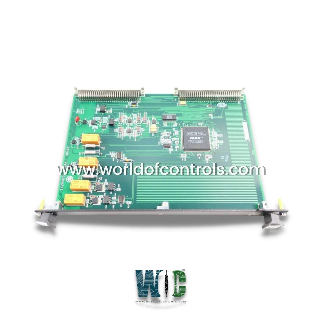
IS200BICRH1A - Bridge Interface Board is available in stock which ships the same day.
IS200BICRH1A - Bridge Interface Board comes in UNUSED as well as REBUILT condition.
To avail our best deals for IS200BICRH1A - Bridge Interface Board, contact us and we will get back to you within 24 hours.
SPECIFICATIONS:
Part Number: IS200BICRH1A
Manufacturer: General Electric
Series: Drive Control
Product type: Bridge Interface Board
FUNCTIONAL DESCRIPTION:
IS200BICRH1A is a Bridge Interface Board manufactured and designed by General Electric as part of the Mark VI Series used in GE Drive Control Systems. This board, which is intended for use in medium voltage Innovation Series Type H drives, is used to create an interface for analog feedback signals between the bridge and drive control. Once scaled and converted to VCO (voltage-controlled oscillator) signals, the signals are routed to the digital signal processor control board. This board, which is intended for use in medium voltage Innovation Series Type H drives, is used to create an interface for analog feedback signals between the bridge and drive control. Once scaled and converted to VCO (voltage-controlled oscillator) signals, the signals are routed to the digital signal processor control board. Its primary function is to process analog feedback signals�such as output voltage, phase current, and other performance metrics�generated within the bridge circuitry. These analog signals are essential for real-time monitoring and closed-loop control of the drive. Upon entering the IS200BICRH1A board, the analog signals are carefully scaled to match the board�s input range and then converted into VCO (Voltage-Controlled Oscillator) signals. This signal transformation results in frequency-based outputs that vary proportionally with the analog input levels.
FEATURES BRIDGE INTERFACE BOARD:
Optically Isolated Digital Inputs and Outputs: The board is equipped with eight optically isolated digital inputs and outputs. These inputs and outputs are electrically isolated using optical components, ensuring signal integrity and protection against electrical noise. This feature enables secure and reliable communication between the board and external devices or components.
Analog Feedback Inputs: The board includes three analog feedback inputs for monitoring and control purposes. It provides one input for the range of 0- 10V and two inputs for the range of 0-20mA. These inputs allow for precise measurement and monitoring of analog signals within the system, providing feedback for accurate control and operation. Backplane Connectors: The board incorporates two backplane connectors, namely P1 and P2, which serve different purposes.
Solid-State Relay Outputs: The board features eight solid-state relay outputs, which are connected to the CTBC (Control Terminal Board Connector) via a CABP (Control Auxiliary Board Panel) board. These relay outputs offer robust switching capabilities and are represented by yellow LEDs for visual indication. Importantly, they are optically separated from the control circuitry, ensuring isolation and protection against potential voltage spikes or interference.
Front Faceplate Design: The front faceplate of the board is equipped with two terminal boards labeled as TB1 and TB2. These terminal boards provide convenient access points for wiring and connections, allowing for organized and structured installation.
LEDs, Fuses, and Test Points: The front faceplate also features eighteen LEDs, serving as indicators for various system statuses and conditions. Additionally, two fuses provide protection against excessive currents or faults. The board is equipped with eight user TP (Test Point) test points, allowing for easy monitoring and troubleshooting during maintenance or testing.
It is worth noting that while the board contains additional test points that are not relevant to the end user, all user-relevant test points are easily accessible through an opening in the front faceplate, ensuring ease of use and accessibility.
WOC offers the largest inventory of replacement parts for GE Drive Control Systems. In addition to supplying unused and rebuilt components, each is backed by a warranty. We also provide expert repair services for faulty boards. Our dedicated team of automation specialists is available 24/7 to support your OEM requirements. Whether you're seeking parts, repairs, or technical guidance, we're here to help. For pricing, availability, or service inquiries, please contact us by phone or email. Our team is ready to assist you.
What is the function of the IS200BICRH1A within GE drive systems?
The IS200BICRH1A serves as a bridge interface module that processes analog feedback signals from the power bridge and converts them into frequency-modulated signals via onboard voltage-controlled oscillators (VCOs). These signals are then transmitted to the DSP (Digital Signal Processor) control board for real-time monitoring and control.
Why are VCO signals used instead of direct analog transmission?
VCO signals offer better immunity to electrical noise and interference, especially in medium-voltage environments. They allow for long-distance transmission of analog information as frequency signals, which the DSP interprets with high accuracy and reliability.
What isolation protection does the bridge interface module provide?
The board incorporates optical and galvanic isolation between the analog input section (bridge side) and the control logic section (DSP side). This ensures protection against high-voltage transients and prevents ground loop issues.