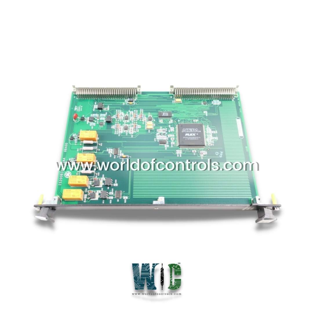
World Of Controls understands the criticality of your requirement and works towards reducing the lead time as much as possible.
IS200BICLH1B - IGBT Drive Source Bridge Interface Board is available in stock which ships the same day.
IS200BICLH1B - IGBT Drive Source Bridge Interface Board comes in UNUSED as well as REBUILT condition.
To avail our best deals for IS200BICLH1B - IGBT Drive Source Bridge Interface Board, contact us and we will get back to you within 24 hours.
SPECIFICATIONS:
Part Number: IS200BICLH1B
Manufacturer: General Electric
Series: Drive Control
Product Type: IGBT Drive Source Bridge Interface Board
Input voltage range: 24-115 V
Input loading range: 4-10 milliamps
Addressing Range: 16 and 32-bits
Technology: Surface Mount
Common Mode Voltage Range: ±5 V
Maximum Lead Resistance: 15Ω
Analog output current: 0-20 mA
Operating temperature: 0 to 60 °C
Storage Temperature: -40 to 80 °C
Relative Humidity: 5 to 95%
Weight: 1lbs
Size: 8.26 cm high x 4.19 cm
Repair: 3-7 Day
Availability: In Stock
Manual: GEI-100264
Country of Origin: United States
FUNCTIONAL DESCRIPTION:
IS200BICLH1B is an IGBT Drive Source Bridge Interface Board manufactured and designed by General Electric as part of the Drive Control Series used in GE Drive Control Systems. The IGBT Drive Source Bridge Interface Board is a circuit board that interfaces between the control circuitry and the insulated gate bipolar transistor (IGBT) power modules in an electrical power system. It is commonly used in applications such as motor drives, power converters, and inverters. The purpose of the IGBT Drive Source Bridge Interface Board is to provide a controlled and isolated interface between the control signals generated by the control circuitry and the high-power IGBT modules. It typically consists of a combination of gate driver circuits, isolation components (such as optocouplers or transformers), voltage level shifting circuits, and protection features.
The gate driver circuits on the interface board are responsible for amplifying and shaping the control signals to provide the necessary drive voltage and current to the IGBT modules. These circuits ensure that the IGBTs switch on and off properly according to the desired operation of the power system. Isolation components are used to provide electrical isolation between the low-voltage control circuitry and the high-voltage IGBT modules. This isolation helps to protect the control circuitry from potential voltage transients, noise, and other disturbances that may be present in the high-power side of the system.
FEATURES:
The specific features of an IGBT Drive Source Bridge Interface Board can vary depending on the application and manufacturer. However, here are some common features you may find:
Gate Driver Circuits: The interface board typically includes gate driver circuits that generate the necessary voltage and current levels to drive the gates of the IGBT modules. These circuits ensure proper switching of the IGBTs and may provide features like adjustable gate voltage, dead-time control, and fault detection.
Isolation Components: Electrical isolation is crucial for safety and noise immunity. The board may incorporate isolation components like optocouplers or transformers to provide isolation between the control circuitry and the high-voltage IGBT modules.
Voltage Level Shifting: If the control signals and IGBT modules operate at different voltage levels, voltage level shifting circuits are used to adapt the signal levels to match the requirements of the IGBTs.
Protection Features: To protect the IGBTs and the overall system, the interface board may have various protection features. These can include short-circuit protection, overvoltage protection, overcurrent protection, and thermal monitoring. These protections help prevent damage to the IGBTs and enhance the safety and reliability of the system.
Fault Monitoring and Reporting: The interface board may include circuitry for monitoring and reporting fault conditions. This can involve detecting faults such as overtemperature, overcurrent, or short circuits, and providing feedback to the control system for appropriate actions or alarms.
Compatibility and Flexibility: The interface board may be designed to work with specific IGBT modules or have the flexibility to accommodate different modules or voltage ratings. It may also offer configuration options, such as adjustable parameters or jumper settings, to cater to different system requirements.
WOC has the largest stock of GE Speedtronic Drive Control System Replacement Parts. We can also repair your faulty boards. WORLD OF CONTROLS can also supply unused and rebuilt backed-up with a warranty. Our team of experts is available round the clock to support your OEM needs. Our team of experts at WOC is happy to assist you with any of your automation requirements. For pricing and availability on any parts and repairs, kindly get in touch with our team by phone or email.
FREQUENTLY ASKED QUESTIONS:
What is the purpose of an IGBT Drive Source Bridge Interface Board?
The purpose of an IGBT Drive Source Bridge Interface Board is to provide a controlled and isolated interface between the control circuitry and the high-power IGBT power modules in applications such as motor drives, power converters, and inverters. It ensures proper switching of the IGBTs and provides protection features for safe and efficient operation.
How do I protect the IGBT modules using an interface board?
Interface boards often include various protection features to safeguard the IGBT modules. These can include short-circuit protection, overvoltage protection, overcurrent protection, and temperature monitoring. These protections help prevent damage to the IGBTs and ensure the safety and reliability of the system.
What is the control logic on this board implemented?
The control logic on this board is implemented in an electronically programmable logic device