SPECIFICATIONS
Part No.: IS200BAIAH1B
Manufacturer: General Electric
Product Type: Application Interface Board
Country of Manufacture: United States (USA)
Availability: In Stock
Series: Drive Control
Functional Description
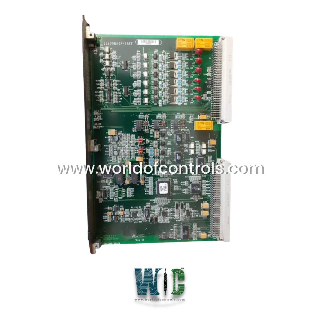
IS200BAIAH1B is an Application Interface Board developed by GE under Drive Control series. The Speedtronic steam and gas turbine management system is now in its fifth version, with triple-redundant backups on protection parameters and crucial controllers. A computer-based operator interface (Windows 2000 or XP) and Ethernet communications are included in the Mark VI.
Features
- Bridge Functionality: It acts as an application interface bridge, facilitating the transmission of signal inputs from terminal boards. It provides earth-ground reference and isolation to ensure accurate and reliable signal processing.
- EEPROM Firmware: Each board is equipped with an embedded Electrically Erasable Programmable Read-Only Memory (EEPROM) chip containing firmware that is factory-programmed and cannot be modified or reprogrammed in the field. This firmware governs the board's operation and functionality.
- Front Panel Design: The front panel of the module is sleek and black in color. It features a single green Light Emitting Diode (LED) labeled "IMOK," indicating the operational status of the board. Additionally, the board number is prominently displayed on the panel, accompanied by a warning advising users to install it in Slot 1 only to prevent potential damage.
- Component Integration: The board includes three relays, six varistors, four jumper switches, three test points, and various integrated circuits. These components collectively contribute to the board's functionality and performance within the turbine management system.
- Backplane Connectors: Two backplane connectors are situated along one edge of the board, facilitating secure and reliable connections within the system architecture.
- Jumper Settings: Proper jumper settings are essential for configuring the board. Jumpers should be positioned in either the VIN (Voltage Input) or 4-20 mA (Milliampere) positions, depending on the specific application requirements.
- Static Protection Measures: To prevent electrostatic discharge (ESD) damage, it is recommended to wear a wrist grounding strap while handling the board. Additionally, during transportation, the board is securely wrapped in anti-static packaging to safeguard against static-related issues.
Board Replacement Procedure
- Switch off the power.
- Carefully disconnect all cables before removing the board. Place one hand on each side of the cable connector that mates with the board-connector for ribbon cables. Pull the cable connector gently with both hands. Pull the pull tab carefully on cables with pull tabs. Loosen the screw at the top of each terminal on a terminal board connector. Pull each wire free gently. Wiring to connectors is removed by gently pulling the connector and depressing the connector latch.
- Take out the standoffs that are holding the board in place. Take out the lock washers. Dropping the lock washers into the board or unit may cause damage.
- Maintaining the board's level, carefully remove it with both hands by pulling the board straight out.
- Remove any jumpers in connector sockets and transfer them to the new board in the same location.
- Replace the standoffs and lock washers with the new board.
- Reattach all cables, making sure that each connector is properly seated at both ends.
The most extensive collection of GE control system components may be found at World of Controls. At any time, our experts are accessible to assist you with your Mark VI requirements. Please contact WOC right away if you require any additional information.
Frequently Asked Questions
What is IS200BAIAH1B?
It is a PWM Input-Output board developed by GE under the Mark VI series.
Where are the backplane connectors located on the board?
The backplane connectors are located on one edge of the board.
What positions should the jumpers be in when working with the board?
The jumpers should be in the VIN or 4-20 mA positions when working with the board.
What precautions should be taken when working with the board?
When working with the board, a wrist grounding strap should be worn at all times to prevent electrostatic discharge.
How is the module wrapped during transit?
The module is wrapped in an anti-static wrap during transit to prevent damage from electrostatic discharge.
