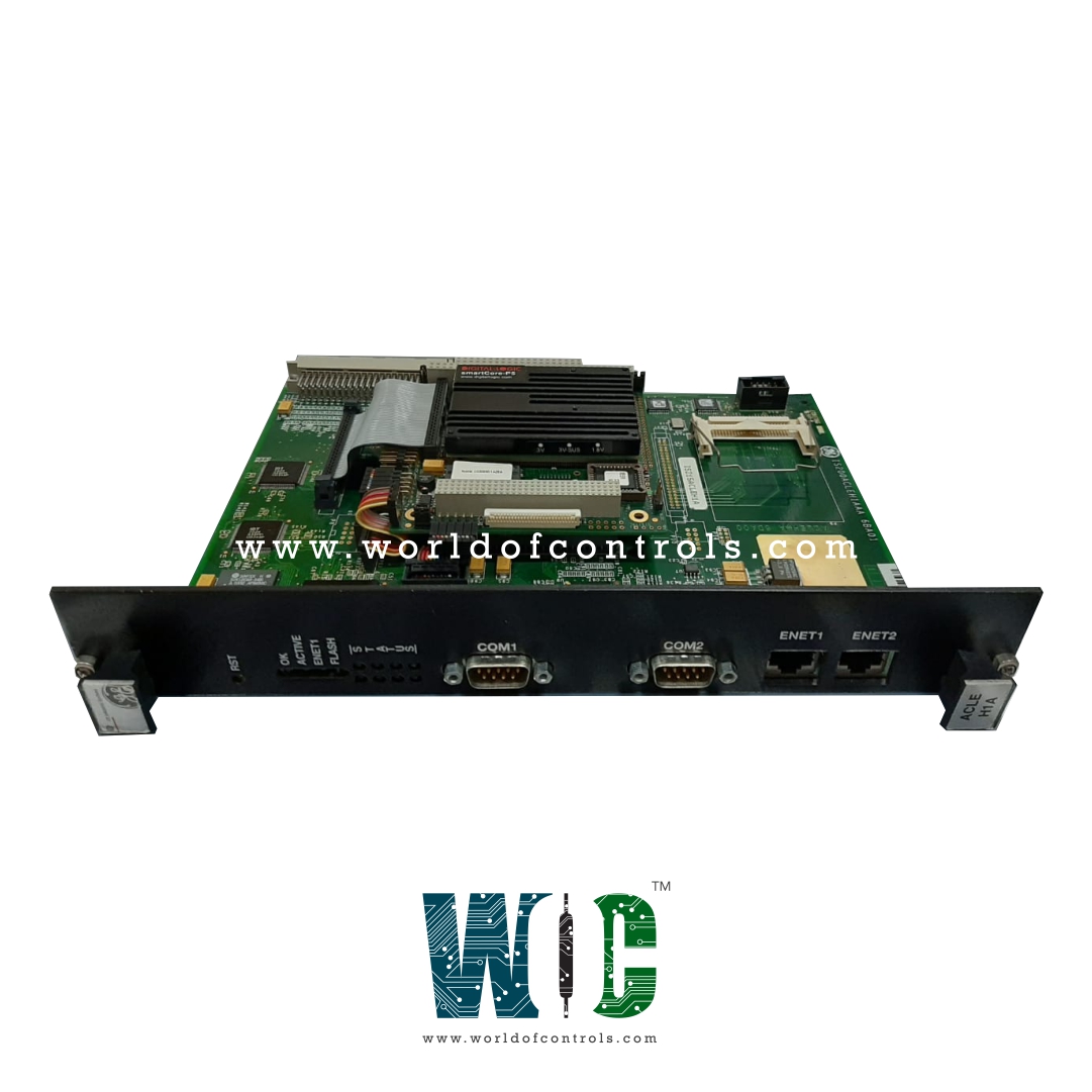
World Of Controls understands the criticality of your requirement and works towards reducing the lead time as much as possible.
IS200ACLEH1A - Application Control Layer Module is available in stock which ships the same day.
IS200ACLEH1A - Application Control Layer Module comes in UNUSED as well as REBUILT condition.
To avail our best deals for IS200ACLEH1A - Application Control Layer Module, contact us and we will get back to you within 24 hours.
Part No: IS200ACLEH1A
Manufacturer: General Electric
Product Type: Application Control Layer Module
Series: EX2100
Availability: In Stock
Country of Manufacture: United States(USA)
Weight: 2.90 lbs
Manual: GEI 100434A
IS200ACLEH1A is an Application Control Layer Module manufactured by General Electric. It is part of EX2100 control systems. It's a microprocessor-based master controller that handles multiple tasks over communication networks like EthernetTM and ISBus. The ACL fits into two half-slots in a standard Innovation Series drive or EX2100 exciter board rack. The control cabinet houses the ACL and the board rack. The P1 connector (4-row 128-pin) plugs into the Control Assembly Backplane Board in drive applications (CABP). The ACL in the EX2100 exciter is mounted in the Exciter Backplane (EBKP).
The ACL's integrated circuits provide the following features:
The BIOS is a 1 MB (128 KB x 8) 5 V flash memory device that mounts in an ACL socket. If no video BIOS is found (if no PC/104 VGA board is installed), the BIOS will redirect the video display to COM1. There are three sections in the flash memory BIOS:
The PCI/ISA Bridge connects to the PCI controller via the CPU Address and LINK buses and controls the following functions:
It manages the compatible interface, which performs the following functions:
The hardware is identified and initialized by the Basic Input/Output System (BIOS). The BIOS directs all output display information to the COM1 serial port during initialization. During the initial boot sequence, the BIOS also supports serial loading of the operating system (compatible with the current GE loader) via the COM1 port. The GE extended BIOS handles the following tasks:
To access individual pin signals on the ACLA board backplane connector P1, a custom extender board is required. These signals are not checked as part of standard in-service testing/troubleshooting procedures, and they are not described in this publication. PC/104 header signals are not defined either. The ACL faceplate contains user connectors. The following tables define the pin signals for these connectors:
WOC has the largest stock of GE Excitation control spare parts . Our team of experts at WOC is happy to assist you with any of your automation requirements. Please contact our staff by phone or email for pricing and availability on any parts and repairs.
What is IS200ACLEH1A?
It is an Application Control Layer Module manufactured by General Electric
What is The function of ACLEH1A?
Application Control Layer Module is a microprocessor-based master controller used to perform multiple duties over communication networks such as EthernetTM and ISBus.
Why is DC utilized as a source of excitation?
To create a static magnetic field, an excitation voltage or current is applied to the field windings of a rotor.