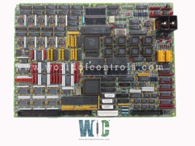
World Of Controls understands the criticality of your requirement and works towards reducing the lead time as much as possible.
DS200TCQBG1AEB - RST Analog I/O Card is available in stock which ships the same day.
DS200TCQBG1AEB - RST Analog I/O Card comes in UNUSED as well as REBUILT condition.
To avail our best deals for DS200TCQBG1AEB - RST Analog I/O Card, contact us and we will get back to you within 24 hours.
SPECIFICATIONS:
Part Number: DS200TCQBG1AEB
Manufacturer: General Electric
Series: Mark V
Product Type: RST Analog I/O Card
Analog Input Types: 4-20 mA
Analog Output Types: 4-20 mA
Mounting Location: R, S, or T
Operating Temperature: 0°C to +60°C
Size: 8.26 cm high x 4.18 cm
Repair: 3-7 days
Availability: In Stock
Weight: 2 lbs
Country of Origin: United States
FUNCTIONAL DESCRIPTION:
DS200TCQBG1AEB is a RST Analog I/O Card manufactured and designed by General Electric as part of the Series used in the R, S, and T cores of the GE Mark V Speedtronic Gas Turbine Control Systems. It interfaces with external analog signals such as 4-20 mA current loops, voltage inputs (0–5 V, ±5 V), RTDs, and thermocouples. Input signals are filtered, isolated, and converted to digital data for processing by the main control processor (DS200SDCC). The board also generates analog outputs, typically 4-20 mA signals, which are sent to field devices such as actuators or control valves. It incorporates signal conditioning circuits and isolation features to maintain signal quality and protect internal electronics. Onboard diagnostic capabilities support fault detection, including open circuits, shorted inputs, and signal integrity issues. The TCQBG1AEB ensures accurate data acquisition and control feedback within the turbine’s analog control loop.
INSTALLATION:
The board is inserted into its assigned slot in the RST rack of the Mark V panel. Proper handling procedures, including the use of electrostatic discharge (ESD) protection, are required to prevent damage. Ribbon cables and terminal blocks must be securely connected according to the system wiring diagram. Once installed, system power can be restored, and hardware diagnostics should be run via the Mark V HMI or toolbox to verify input/output functionality. Configuration parameters must match system requirements, including signal scaling and sensor types. Calibration may be necessary depending on the type of input signals connected.
OPERATION:
The board acquires analog inputs from connected field devices, performs signal conditioning and digitization, and transmits the processed data to the RST control processor for computation. The board simultaneously receives digital control instructions from the processor and outputs corresponding analog signals to field equipment. All analog channels are continuously monitored for status and integrity. Synchronization with the triple modular redundant (TMR) system ensures high availability and fault tolerance. If a channel failure or out-of-range condition occurs, the board reports the error to the system diagnostics. Continuous monitoring and signal processing are essential for closed-loop control and safe turbine operation.
WOC maintains the largest inventory of OEM Replacement Parts for GE Speedtronic Control Systems. We also specialize in expert repair services for malfunctioning boards and offer a wide range of unused and refurbished units—all covered by warranty. Our experienced team is available 24/7 to assist with your automation and OEM needs. For inquiries regarding pricing, availability, or repairs, please contact us by phone or email.
What types of analog signals does the RST Analog I/O Card support?
It supports multiple analog input signals, including 4–20 mA current loops, 0–5 V and ±5 V voltage signals, RTDs, and thermocouples. Outputs are typically 4–20 mA analog signals used for controlling actuators or indicators.
Why is a particular analog output not responding to control commands?
Check the control logic to ensure an output signal is being generated. Use the HMI or toolbox software to monitor output command values. Inspect the output wiring for open or short circuits. If the card is receiving the correct command but the field device does not respond, measure the output signal directly at the card terminals.
What should I do if analog output signals do not respond to control commands?
Verify output commands via system software, check output wiring and field devices, measure output signals at the card terminals, and inspect the card for faults. Swap the card if hardware failure is suspected.