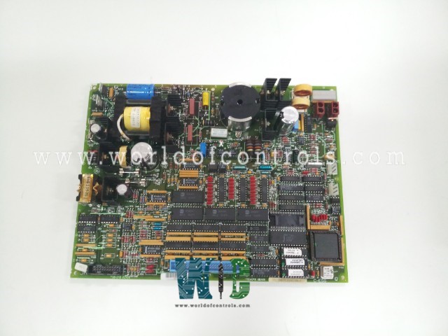
World Of Controls understands the criticality of your requirement and works towards reducing the lead time as much as possible.
DS200TCEAG2BTF - Emergency Overspeed Board is available in stock which ships the same day.
DS200TCEAG2BTF - Emergency Overspeed Board comes in UNUSED as well as REBUILT condition.
To avail our best deals for DS200TCEAG2BTF - Emergency Overspeed Board, contact us and we will get back to you within 24 hours.
SPECIFICATIONS:
Part Number: DS200TCEAG2BTF
Manufacturer: General Electric
Series: Mark V LM
Board rating: 125 V DC
Product Type: Emergency Overspeed Board
Impedance to the ground: 75 Ohms
Overspeed Trip: J28/J29
Connectors: J7, JK, JL, JW, JX1
Redundancy: Dual
Power Requirements: +5 V dc, 6 A
Operating temperature: -30 to +65°C
Size: 30.48cm High x 21.33cm
Mounting: 4 mounting Holes
Repair: 3-7 days
Availability: In Stock
Country of Origin: United States
FUNCTIONAL DESCRIPTION:
DS200TCEAG2BTF is an Emergency Overspeed Board manufactured and designed by General Electric as part of the Mark V LM Series used in GE Speedtronic Control Systems. The Emergency Overspeed Board (TCEA), located in the Protective Core
TCEA CONNECTORS:
TCEA CONFIGURATION:
Hardware: The TCEA boards feature several hardware jumpers for configuration and testing purposes. Jumpers J1 and J31 are used for factory testing, while J2 and J3 are designated for IONET termination resistors. Jumpers J4, J5, and J6 are responsible for setting the IONET address for each TCEA board. Overspeed trip frequency settings are adjusted using jumpers J12 through J21 for the high-pressure shaft and J8 through J11, as well as J22 through J27, for the low-pressure shaft. The actual configuration of these settings is performed through the I/O configuration software. Additionally, jumpers J28 and J29 cause
Software: The IO Configuration Editor is used to set the base speed and overspeed values for both the high and low pressure shafts, as well as calculate the hardware jumper settings for trip frequency. It also allows for the selection of pulse rate information from the Ultra Violet (UV) flame detectors and the configuration of auto-synchronization permissive values.
TCEA AUTOMATIC SYNCHRONIZING CIRCUIT:
The bus and generator voltages from the PTBA terminal board are routed through the JV connector to the TCEB board and then transferred via the JMP connector to the TCEA board. Embedded software in the TCEA's EPROMs handles both speed and voltage matching. After verifying that generator and line voltages and frequencies are within the limits set by the I/O Configuration constants, the TCEA board issues a permissive signal to close the breaker. Additionally, the STCA board performs an independent synchronization check and sends a logic signal to the TCEA board, which must also be valid for breaker closure to occur.
WOC has the largest stock of OEM Replacement Parts for GE Speedtronic Control Systems. We can also repair your faulty boards and supply unused and rebuilt boards backed up with a warranty. Our team of experts is available around the clock to support your OEM needs. Our team of experts at WOC is happy to assist you with any of your automation requirements. For pricing and availability on parts and repairs, kindly contact our team by phone or email.
What is the Emergency Overspeed Board (TCEA)?
The Emergency Overspeed Board (TCEA) is a vital component in the turbine control system, responsible for monitoring turbine shaft speed and initiating emergency shutdowns if an overspeed condition is detected. It serves as a core part of the turbine’s protective logic.
How do the boards transmit their data?
The boards condition and scale their input signals and send the data over the IONET to the STCA board in the R1 core via the JX1 connector. The Y and Z boards transfer their information using the JX1 and JX2 connectors through the X board.
How does the TCEA board communicate with the system?
Communication between the TCEA boards and the rest of the system occurs via daisy-chained IONET connections through connectors JX1 and JX2. These connections allow the TCEA boards to send and receive critical data to the I/O Engine and Control Engine in the