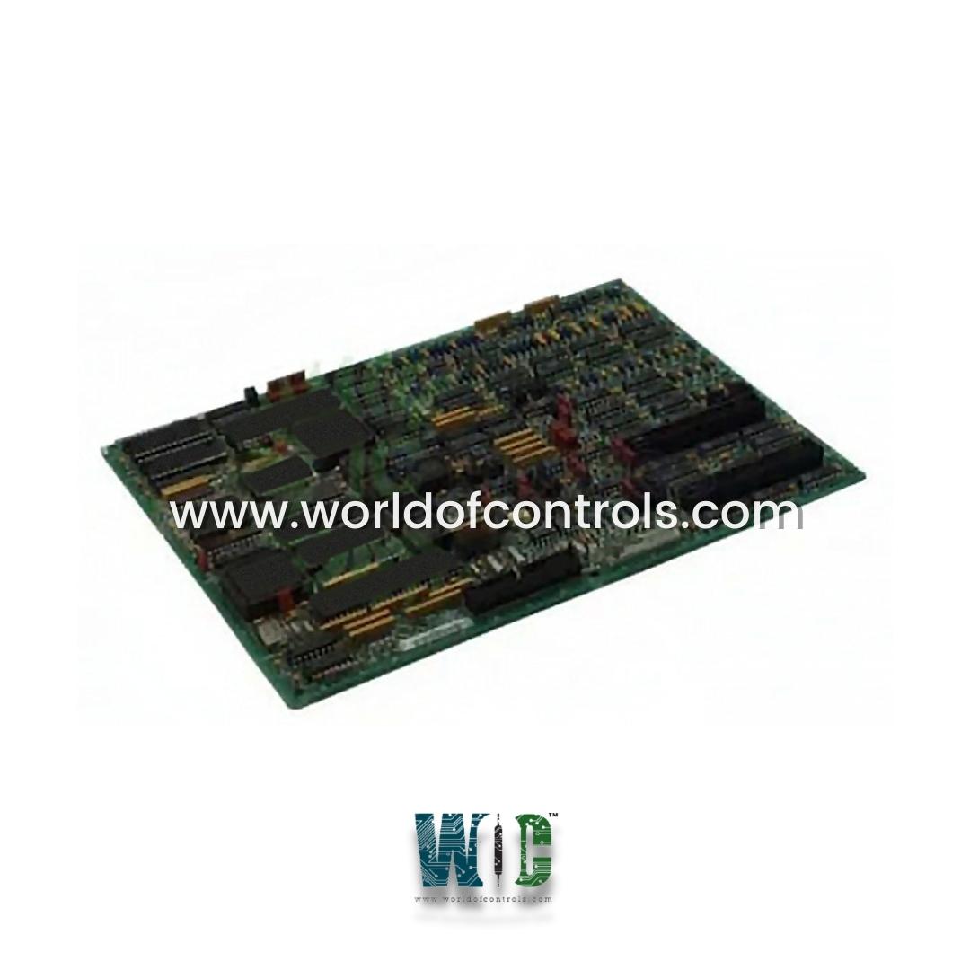
DS200TCCBG2B - Common Extended Analog I/O Board

DS200TCCBG2B - Common Extended Analog I/O Board DS200TCCBG2B - Common Extended Analog I/O Board

World Of Controls understands the criticality of your requirement and works towards reducing the lead time as much as possible.

DS200TCCBG2B - Common Extended Analog I/O Board is available in stock which ships the same day.

DS200TCCBG2B - Common Extended Analog I/O Board comes in UNUSED as well as REBUILT condition.

To avail our best deals for DS200TCCBG2B - Common Extended Analog I/O Board, contact us and we will get back to you within 24 hours.

SPECIFICATIONS:

Part Number: DS200TCCBG2B
Manufacturer: General Electric
Series: Mark V LM
Product Type: Common Extended Analog I/O Board
Number of channels: 24
Power supply voltage: 28 V dc
Voltage Range: 14 to 32 V dc
Mounting: DIN-rail mounting
Technology: Surface mount
Operating temperature: -30 to 65°C
Size: 30 cm high x 18 cm
Repair: 3-7 Day
Availability: In Stock
Country of Origin: United States

FUNCTIONAL DESCRIPTION:

DS200TCCBG2B is a Common Extended Analog I/O Board manufactured and designed by General Electric as part of the Mark V LM Series used in GE Speedtronic Gas Turbine Control Systems. The Common Extended Analog I/O Board (TCCB) enhances the capability to process various analog input signals originating from the TBCB terminal Board situated on the core and the TCEB board in the core. These signals consist of 4-20 mA/0.1 mA inputs, RTDs, generator and bus voltage inputs, and line current inputs. The STCA board retrieves these processed signals through the 3PL connector.

TCCB CONNECTORS:

2PL - Distributes power from the TCPS board in the core.
3PL - The Data Bus between the STCA, TCCA, and TCCB boards in core . Conditioned signals are carried on 3PL for transferring to the COREBUS.
JHH - Carries the 4.20 mA/0.1 mA input signals from the TBCB terminal board.
JII - Carries the RTD input signals from the TBCB terminal board.
JMP - Carries the potential and current transformer (PT and CT) signals from the TCEB board in the core.

TCCB RTD CIRCUIT:

The circuitry that supplies excitation to the RTDs from the TBCB terminal board is located on the TCCB board. A steady current is sent through the RTD and when the temperature changes, the resistance changes causing the voltage on the RTD to change. The TCCB board measures, scales, and conditions the voltages. The RTD signals are read from the TBCB terminal board by the TCCB board over the JCC and JDD connectors. The TCCB board sends the signals to the I/O Engine via the 3PL connector. The type of RTD is selected using I/O configuration constants.

WOC has the largest stock of GE Speedtronic Control System Replacement Parts. We can also supply unused and rebuilt backed-up with a warranty. Our team of experts is available round the clock to support your OEM needs. Our team of experts at WOC is happy to assist you with any of your automation requirements. For pricing and availability on any parts and repairs, kindly contact our team by phone or email.

FREQUENTLY ASKED QUESTIONS:

What is the difference between single-ended and differential inputs/outputs on an Extended Analog I/O Board?

Single-ended inputs/outputs measure signals concerning a common ground reference, whereas differential inputs/outputs measure the voltage difference between two signal lines. Differential inputs are often used in noisy environments or to improve common-mode rejection, resulting in more accurate measurements.

How do I calibrate an Extended Analog I/O Board for accurate measurements?

Calibration procedures vary depending on the board and application but typically involve applying known input signals and adjusting calibration parameters (such as gain and offset) to match the measured outputs to the expected values. Some boards may provide built-in calibration routines or software tools to assist with this process.

What are the power requirements for Extended Analog I/O Boards?

The power requirements for Extended Analog I/O Boards vary depending on the board's specifications and features. They typically require a stable power supply within a specified voltage range, and some boards may also have specific current requirements. Be sure to check the datasheet and specifications of the board for detailed information on power requirements.