World Of Controls understands the criticality of your requirement and works towards reducing the lead time as much as possible.
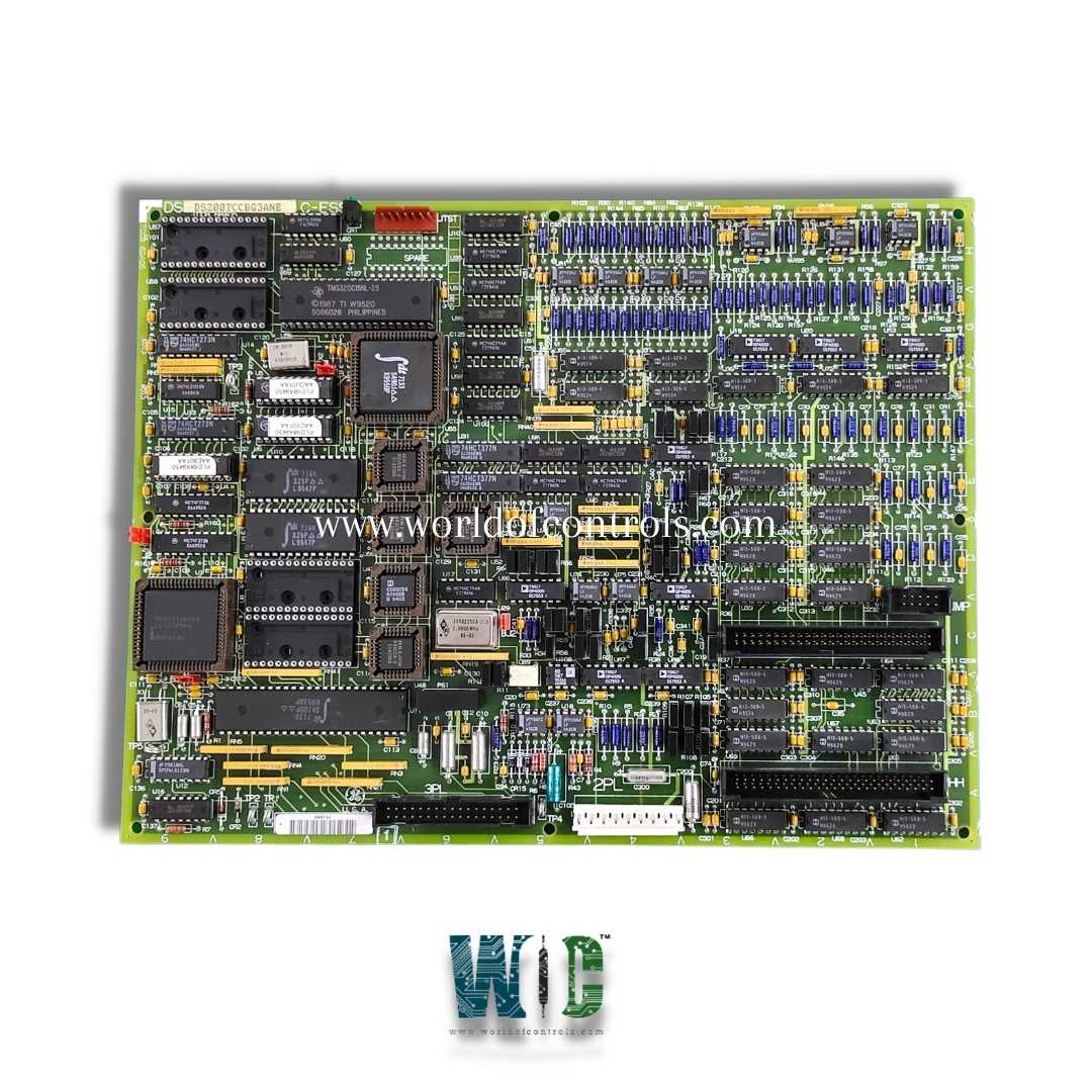
DS200TCCBG2A - Common Extended Analog I/O Board is available in stock which ships the same day.
DS200TCCBG2A - Common Extended Analog I/O Board comes in UNUSED as well as REBUILT condition.
To avail our best deals for DS200TCCBG2A - Common Extended Analog I/O Board, contact us and we will get back to you within 24 hours.
SPECIFICATIONS:
Part Number: DS200TCCBG2A
Manufacturer: General Electric
Series: Mark V LM
Product Type: Common Extended Analog I/O Board
Number of channels: 24
Power supply voltage: 28 V dc
Voltage Range: 14 to 32 V dc
Mounting: DIN-rail mounting
Technology: Surface mount
Operating temperature: -30 to 65 Deg C
Size: 30 cm high x 18 cm
Repair: 3-7 Days
Availability: In Stock
Country of Origin: United States
FUNCTIONAL DESCRIPTION:
The DS200TCCBG2A is a Common Extended Analog I/O Board (TCCB) manufactured by General Electric as part of the Mark V LM Series for GE Speedtronic Gas Turbine Control Systems. The TCCB provides precise scaling and signal conditioning for additional analog inputs and outputs, enabling the integration of various field signals.
It interfaces with the TBCB Terminal Board on the R5 core and the TCEB Board on the P1 core. The TCCB supports multiple types of analog inputs, including 4�20 mA and 0�1 mA current signals, RTDs for temperature measurement, generator and bus voltage inputs, and line current inputs. All signals are accurately captured and standardized for processing.
After receiving the signals, the TCCB conditions and scales them to meet system requirements, including noise filtering and signal range adjustment. The processed signals are then sent to the STCA Board via the 3PL connector, where they are used for monitoring, control, and protection functions. This ensures reliable integration of multiple analog I/O channels while maintaining system accuracy and performance.
TCCBG2A CONFIGURATION:
Hardware: The hardware jumpers J1, J2, J3, J4, and J5 are used to provide the generator and bus voltage monitoring functions and the line current monitoring function in the Mark V LM. Hardware jumper J14 is used to connect the RS232 serial port to DCOM. Hardware jumpers J15 and J16 are used for testing purposes.
Software: I/O configuration constants for the RTDs, mA inputs, generator bus voltage, and line current settings are entered in the I/O Configuration Editor located on the HMI as described below.
TCCBG2A 4-20 MA INPUT CIRCUIT:
The TCCBG2A board contains the circuitry that provides excitation current to RTDs connected through the TBCB terminal board. A constant current flows through each RTD, and as the temperature changes, the RTD�s resistance varies, causing a corresponding change in voltage. The TCCB board measures these voltage changes, then scales and conditions the signals for accurate processing.
RTD signals are transmitted from the TBCB terminal board to the TCCB board via the JCC and JDD connectors. After conditioning, the TCCB forwards the signals to the I/O Engine through the 3PL connector. The specific type of RTD being used is determined through I/O configuration constants, allowing the system to accurately interpret and process the temperature data.
WOC maintains the largest inventory of GE Speedtronic Control System replacement parts, ensuring that you have access to the components you need when you need them. We supply both unused and professionally rebuilt parts, all backed by a warranty to give you peace of mind and guarantee reliability. Our team of industry experts is available 24/7 to support all your OEM and automation requirements, providing guidance, technical assistance, and solutions tailored to your specific needs. Whether you are looking for parts, repairs, or system support, we are committed to delivering prompt and dependable service. For pricing, availability, or technical inquiries, please reach out to our team via phone or email, and we will be happy to assist you.
What is the DS200TCCBG2A Board?
The DS200TCCBG2A is a Common Extended Analog I/O Board from GE’s Mark V LM Series. It provides scaling and signal conditioning for additional analog inputs and outputs in GE Speedtronic Gas Turbine Control Systems. The board ensures accurate integration of field signals for monitoring, control, and protection.
What types of signals does theTCCBG2A handle?
The TCCB supports analog inputs such as 4–20 mA and 0–1 mA current signals, RTDs for temperature measurement, generator and bus voltages, and line currents. It conditions and scales all signals to be compatible with the system’s processing requirements. This ensures reliable and accurate data for system operations.
How does the TCCBG2A process RTD signals?
The TCCB supplies a constant excitation current to RTDs, causing a voltage change as resistance varies with temperature. It measures, scales, and conditions these voltages for accurate processing. The signals are then transmitted to the I/O Engine via the 3PL connector for system use.
How are signals transmitted to theTCCBG2A?
Signals from the TBCB terminal board are sent to the TCCB via the JCC and JDD connectors. After conditioning, the TCCB forwards the signals to the STCA or I/O Engine. This setup allows seamless integration of multiple analog channels.
How can I contact WOC for pricing or support?
WOC team of experts is available 24/7 for technical support, parts inquiries, and system assistance. You can contact us via phone or email for pricing, availability, or technical guidance. Our team provides prompt and dependable service tailored to your needs.