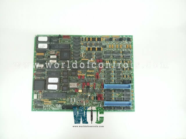
SPECIFICATIONS
Part No.: DS200TCCBG1ALC
Manufacturer: General Electric
Country of Manufacture: United States of America (USA)
Product Type: Analog I/O Board
Availability: In Stock
Series: Mark V
Functional Description
DS200TCCBG1ALC is an analog I/O board developed by GE. It is a part of the Mark V control system. The Common Extended Analog I/O Board (TCCB) is a component in advanced control systems, responsible for the scaling and conditioning of additional analog input/output signals. These signals are read from the TBCB terminal board, which is mounted on the R5 core, and the TCEB board, located in the P1 core. This functionality is essential for accurate signal processing and integration within the system.
Features
- Current Inputs: 4-20 mA Inputs are standard current loop signals used for transmitting process variables in industrial automation systems. 0-1 mA Inputs lower current signals, often used in specific instrumentation applications.
- Resistance Temperature Detectors (RTDs): RTDs are sensors used to measure temperature by correlating the resistance of the RTD element with temperature. The TCCB handles signals from RTDs, ensuring accurate temperature measurements are relayed to the system.
- Generator Voltage Inputs: These inputs monitor the voltage generated by the system, ensuring that it remains within the desired range.
- Bus Voltage Inputs: These inputs monitor the voltage on the electrical bus, which distributes power within the system.
- Line Current Inputs: These inputs measure the current flowing through power lines, which is critical for monitoring and controlling power distribution.
- Scaling and Conditioning: The board scales and conditions these various input signals to ensure they are within the appropriate ranges and formats for further processing by the system. This conditioning is vital for maintaining signal integrity and accuracy.
- 3PL Connector: The scaled and conditioned signals are then transmitted to the STCA board via the 3PL connector. The 3PL connector provides a reliable and efficient means of transferring these processed signals, ensuring seamless integration within the control system.
Hardware Configuration
- Jumper J1, J2, J3, J4, and J5: These jumpers configure the monitoring functions for generator voltage, bus voltage, and line current. Proper configuration of these jumpers ensures accurate voltage and current measurements, which are crucial for system stability and performance.
- RS232 Serial Port Connection: Jumper J14 connects the RS232 serial port to DCOM (Distributed Component Object Model). DCOM is a Microsoft technology for communication between software components distributed across networked computers. This connection enables serial communication between the Mark V LM system and other devices or control systems.
- Testing Purposes: Jumpers J15 and J16 jumpers are reserved for testing purposes. Adjusting these jumpers allows technicians to perform diagnostic tests and verify the proper operation of the system components.
Software Configuration
- I/O Configuration Constants: RTDs Configuration constants for Resistance Temperature Detectors (RTDs) must be entered. These constants define how the system interprets the temperature readings from the RTDs. Milliamp Inputs Configuration constants for milliamp inputs (4-20 mA and 0-1 mA) are also required. These constants ensure that the system correctly processes the current signals from various sensors and devices.
- Voltage and Current Settings: Configuration constants for generator voltage, bus voltage, and line current must be specified. These settings are crucial for accurate monitoring and control of electrical parameters within the system.
- I/O Configurator: These configuration constants are entered using the I/O Configurator, a software tool located on the operator interface. The I/O Configurator provides a user-friendly interface for entering and managing these settings, ensuring that all inputs are correctly configured for optimal system performance.
The WOC team is always available to help you with your Mark V requirements. For more information, please contact WOC.
Frequently Asked Questions
What is DS200TCCBG1ALC?
It is an analog I/O board developed by GE under the Mark V series.
What is the purpose of hardware jumpers J15 and J16?
Jumpers J15 and J16 are designated for testing purposes. They allow technicians to perform diagnostic tests and verify the operation of various system components.
How are I/O configuration constants entered for RTDs, milliamp inputs, and voltage/current settings?
I/O configuration constants for RTDs, milliamp inputs, generator, and bus voltage, and line current settings are entered using the I/O Configurator, which is accessible through the operator interface. This tool allows users to input and manage these settings to ensure accurate system performance.
What role do configuration constants play in the system's operation?
Configuration constants define how the system processes and interprets data from RTDs, milliamp inputs, and voltage/current sensors. Proper configuration ensures that the system accurately monitors and controls various operational parameters.
