World Of Controls understands the criticality of your requirement and works towards reducing the lead time as much as possible.
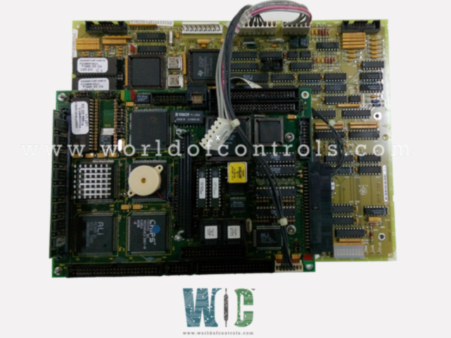
DS200STCAG1A - Turbine Communication Board is available in stock which ships the same day.
DS200STCAG1A - Turbine Communication Board comes in UNUSED as well as REBUILT condition.
To avail our best deals for DS200STCAG1A - Turbine Communication Board, contact us and we will get back to you within 24 hours.
Part No.: DS200STCAG1A
Manufacturer: General Electric
Country/Region of Manufacture: United States of America
Product Type: Turbine Communication Board
Series: Mark V
DS200STCAG1A is a Turbine Communication Board developed by GE. It serves as the I/O cores' IONET master. There is an STCA board for every I/O core. The bus connections J1 and J3 are used to read signals from the various connectors, condition them, and then write them to the I/O Engine on the UCPB daughterboard. The JEE connector is used to write the signals to the COREBUS connections on the QTBA or CTBA boards.
The factory test points are enabled by hardware jumper JP2. The voltage required for the flash EPROM is chosen by hardware jumper JP4. For details on the hardware jumper settings for this board, consult Appendix A and the operator interface's hardware jumper panel. Software. The I/O Configuration Editor on the operator interface is used to enter the I/O configuration constants for the pulse rate inputs, compressor stall detector, and synchronization settings.
The pulse rate inputs obtained from the TCQC board are scaled and conditioned by the STCA board. These signals come from magnetic pick-up devices, and the QTBA, TBQB, and/or PTBA terminal boards write their signals to the TCQC board. The high pressure shaft pulse rate inputs are read by the core. Each core's pulse rate inputs are separate and serve various functions.
The 19PL connector is used to read the generator and bus voltage inputs from the TCQC board. These signals are sent from the core's PTBA terminal board to the core's TCTG board via the JN connection. The signals are then sent from the TCTG board to the TCQA board in the core through the JDR/S/T connectors to the JD connector.
WOC experts are always available to help you with your GE turbine control component requirements. For more information, please contact WOC.
How are Signals Read on DS200STCAG1A?
Signals are taken from a variety of connectors on the DS200STCAG1A, conditioned, and written to the I/O Engine on the UCPB daughterboard through bus connectors J1 and J3.
What Does DS200STCAG1A do for pulse rate inputs?
Pulse rate inputs read from the TCQC board are scaled and conditioned.
What is the relationship between DS200STCAG1A and IONET?
IONET is an internal Mark V LM panel communication network that allows data to be exchanged between STCAG1A, the TCDA boards, and the TCEA boards.