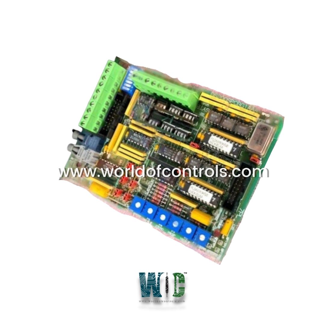
World Of Controls understands the criticality of your requirement and works towards reducing the lead time as much as possible.
DS200SPCBG1A - Multi-bridge Signal Processing Card is available in stock which ships the same day.
DS200SPCBG1A - Multi-bridge Signal Processing Card comes in UNUSED as well as REBUILT condition.
To avail our best deals for DS200SPCBG1A - Multi-bridge Signal Processing Card, contact us and we will get back to you within 24 hours.
Part Number: DS200SPCBG1A
Manufacturer: General Electric
Series: Drive Control
Product Type: Multi-bridge Signal Processing Card
Power Requirements: +5 V dc, 6 A
Power supply voltage: 28 V dc
Operating temperature: -30 to +65 degrees Celsius
Availability: In Stock
Country of Manufacturer: United States (USA)
Manual: GEI-100172A
DS200SPCBG1A is a multi-bridge signal processing card developed by GE. It is a part of General Electric Drive control system. In multi-bridge drive systems, the SPCB interfaces between the dmc SDCC card and the MBI-IA boards. A multi-bridge signal processing card is a type of hardware card designed to process multiple signals simultaneously. This type of card is commonly used in applications such as digital signal processing, telecommunications, and data acquisition systems. The card typically includes multiple analog-to-digital converters (ADCs) and digital-to-analog converters (DACs), along with digital signal processing (DSP) capabilities. The ADCs convert incoming analog signals into digital form, while the DACs convert digital signals back into analog form for output.
The DSP capabilities of the card allow for advanced signal processing functions such as filtering, modulation, demodulation, and frequency analysis. The multi-bridge design allows for multiple signals to be processed simultaneously, increasing overall processing efficiency. Multi-bridge signal processing cards can be used in a variety of applications, such as in medical imaging, telecommunications networks, and industrial automation systems. They are often used in conjunction with specialized software applications for configuring and controlling the processing functions of the card.
WOC is happy to assist you with any of your GE requirements. Please contact us by phone or email for pricing and availability on any parts and repairs.
What is DS200SPCBG1A?
It is a multi-bridge signal processing card developed by GE
What does SDCC refer to?
SDCC refers to the Signal Data and Control Card, which is an electronic circuit board that is used for control and communication purposes in industrial processes.
What are encoder feedback signals?
Encoder feedback signals are electrical signals that are generated by an encoder device and provide information about the position and/or speed of a motor or other rotating machinery.
What is an optocoupled differential interface?
An optocoupled differential interface is a circuit that uses optical signals to transfer electrical signals across an isolation barrier. It is commonly used in industrial control applications to protect sensitive electronic components from electrical noise or voltage spikes.