SPECIFICATIONS
Part No.: DS200SHVMG1BB
Manufacturer: General Electric
Country of Manufacture: United States of America (USA)
Product Type: SCR High Voltage M-Frame Interface Board
Availability: In Stock
Series: EX2000
Functional Description
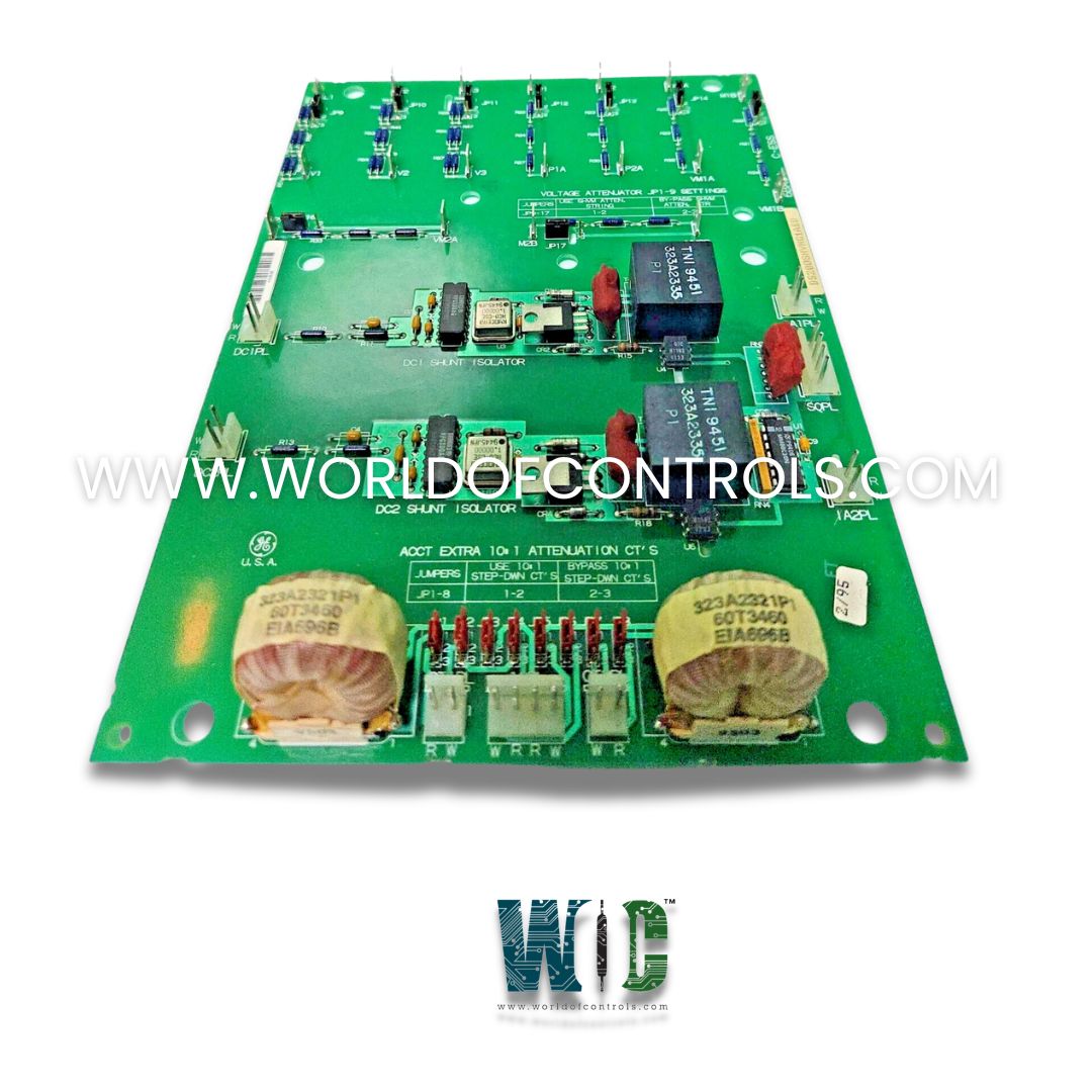
DS200SHVMG1BB is a SCR High Voltage M-Frame Interface Board developed by GE. It is a part of EX2000 excitation system. Its primary function is to interface high-voltage SCR bridge signals with the system’s power supply and control components. It plays a vital role in ensuring signal compatibility, electrical isolation, and measurement integrity within the drive and excitation subsystem.
Features
- Shunt Signal Conversion: The board converts analog shunt voltage signals in the range of –500 mV to +500 mV into corresponding differential-frequency outputs ranging from 0 to 500 kHz. These frequency-modulated signals are then transmitted to the DCFB or SDCI board, where they are interpreted and used for monitoring current flow through the SCR bridge. Frequency-based encoding helps reduce noise interference and enhances measurement reliability over longer distances within the control enclosure.
- Current Attenuation via Transformer Selection: The board is equipped with jumper-selectable 10:1 current transformers, allowing additional attenuation of input signals when required. These transformers enable engineers to scale high current levels down to manageable ranges for signal processing. The jumper configuration makes it adaptable for use in different load or drive conditions, offering flexibility in tuning current sensitivity according to the specific application.
- Voltage Attenuation: To protect the system and ensure compatibility with low-voltage control electronics, the board also includes circuitry to attenuate high-voltage signals from three critical sources:
- AC line inputs
- Motor armature
- SCR bridge voltages
Hardware Features
The board integrates multiple shielded signal paths, isolation mechanisms, and high-frequency conversion circuits designed to operate reliably in high-electromagnetic-noise environments typical of excitation and drive systems. The use of differential signaling, transformer-based attenuation, and frequency-based output makes it ideal for transmitting feedback signals over complex control architectures without degradation or distortion.
DC Bridge Shunt Isolator Circuits
- The board includes two floating shunt isolator circuits, one for the positive (DC+) leg and one for the negative (DC−) leg of the SCR power bridge. These circuits are designed to interface with shunt resistors installed in the DC circuit of the power bridge, which generate low-level voltage signals (typically in the range of –500 mV to +500 mV) proportional to the current flowing through the DC link.
- Each isolator circuit features a voltage-controlled oscillator (VCO) that converts the analog shunt voltage into a corresponding frequency signal in the range of 0 to 500 kHz. This frequency-modulated signal offers a robust, noise-immune method of transmitting current data to the DCFB (DC Feedback) board for further processing. The use of frequency rather than voltage for signal transmission is particularly advantageous in high-electromagnetic-noise environments typical of power electronics systems.
- An important feature of these circuits is that they are electrically floating, meaning the input side of each isolator floats to the electrical potential of the bridge (either DC+ or DC−), while maintaining isolation from the control ground. This isolation protects sensitive control electronics and enables accurate current measurement without introducing common-mode errors or risking ground loops.
AC Current Transformers (ACCTs)
- In addition to handling DC feedback, the SHVM board also supports monitoring of AC line currents on Phase A and Phase C using AC current transformers (ACCTs). These are often used for monitoring incoming power quality or implementing phase-based control logic.
- To accommodate different current ranges and maintain compatibility with downstream boards (such as the SDCI or DCFB Power Supply Boards), the SHVM includes jumper-selectable 10:1 attenuation for the ACCT signals. This attenuation reduces the amplitude of the CT signals by a factor of 10 when necessary.
- Attenuation becomes essential when the ACCT secondary current exceeds 144 mA. This threshold is based on the power dissipation limits of the burden resistors located on the SDCI and DCFB boards, which are not designed to safely handle currents higher than 144 mA. Applying attenuation reduces the burden resistor stress and prevents overheating or component failure.
- Conversely, when the ACCT secondary current is below 144 mA, attenuation should be bypassed, ensuring full signal fidelity and eliminating the unnecessary loss of resolution. The ability to jumper-select this setting allows the SHVM board to be adapted to different ACCT models and current levels without requiring board-level modifications.
The WOC team is always available to help you with your EX2000 requirements. For more information, please contact WOC.
Frequently Asked Questions
What is DS200SHVMG1BB?
It is a SCR High Voltage M-Frame Interface Board developed by GE under the EX2000 series.
What happens if I leave the attenuators bypassed when using 600 V line voltage?
Leaving the attenuators bypassed when high line voltage is present can overload the signal processing circuits, causing inaccurate voltage readings, signal clipping, or potential board damage.
What do P1 and P2 refer to on the SHVM board?
P1 and P2 are the terminals used to monitor the positive and negative bridge voltages. They feed the feedback voltage signals into the control system via internal resistor string attenuators.
