World Of Controls understands the criticality of your requirement and works towards reducing the lead time as much as possible.
DS200PCCAG6A - DC2000 Power Connect Card is available in stock which ships the same day.
DS200PCCAG6A - DC2000 Power Connect Card comes in UNUSED as well as REBUILT condition.
To avail our best deals for DS200PCCAG6A - DC2000 Power Connect Card, contact us and we will get back to you within 24 hours.
SPECIFICATIONS:
Part Number: DS200PCCAG6A
Manufacturer: General Electric
Product Type: Power Connect Card
Series: Mark V
Input Voltage: 24 VDC
Output Voltage: 12 VDC
Power Rating: 2000W
Efficiency: 90%
Operating Temp: -20°C to 70°C
Dimensions: 160 x 100 x 50 mm
Weight: 1.5 kg
Output Ripple: 100 mV peak-to-peak
Control Interface: I2C, Digital PWM
Mounting: DIN Rail Mounting
Protection: Overcurrent, Overvoltage
Availability: In Stock
Country of Origin: USA
FUNCTIONAL DESCRIPTION:
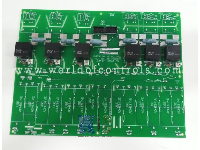
DS200PCCAG6A is a DC2000 Power Connect Card manufactured and Designed by General Electric as part of the Mark V Series used in GE Gas Turbine Control Management Systems. The DS200PCCA Power Connect Card (PCCA) provides an interface between the drive’s control circuitry and the SCR power bridge. The PCCA board uses pulse transformers to provide a gate drive to the SCR bridge. For low-to-medium horsepower controllers, the PCCA board also includes snubber circuits to control spikes across the ac lines, dc bus, and gate drivers. For higher horsepower controllers, some or all of the snubber circuits are omitted from the PCCA board and are located elsewhere in the system.
BOARD GROUPS:
The PCCA board has ten group numbers. The group number used in a system is determined by the system voltage, frame size, and whether the system uses regenerative or non-regenerative power conversion. Table 1 summarizes the applications of the various PCCA board group numbers. The armature voltage scaling depends on which PCCA board group number is used:
The PCCA board has four wire jumpers, designated JP1, JP2, WP3, and WP4 that select system voltage and determine snubber capacitor connections.
CONFIGURABLE JUMPERS (JP and WP):
The PCCA board has four wire jumpers, designated JP1, JP2, WP3, and WP4. Jumpers JP1 and JP2 must be connected to the appropriate stab terminals P3 through P10, as determined by the card group number and system voltage. Jumpers WP3 and WP4 are used to connect stab terminals P2A to P2B, and P1A to P1B, respectively. These jumpers are used to select whether the PCCA snubber capacitors are connected to the same point on the power bridge as the voltage feedback channel.
BOARD CONNECTORS:
The PCCA board sends forward and reverse gate pulse signals to the SCR bridge via twelve plug connectors, 1RPL − 6RPL and 1FPL − 6FPL, and communicates with the power supply board via one additional plug connector, 5PL. See Figure 1 for an PCCA board layout diagram showing the locations of these connectors and see Tables 4 and 5 for the signal descriptions of the connectors.
WOC maintains the largest inventory of Replacement parts for GE Speedtronic Gas Turbine Control systems. Additionally, we offer warranty-backed unused and rebuilt boards as well as board repairs for damaged ones. For your OEM needs, our team of professionals is available around the clock. We at WOC are happy to help you with any automation needs you may have. Please contact our team by phone or email for pricing and availability on any components and repairs.
What is the Power Connect Card used for?
The Power Connect Card is a critical component in GE Gas Turbine Control Management Systems, interfacing between the turbine’s control circuitry and the SCR power bridge. It ensures proper gate drive and controls spikes across the AC lines, DC bus, and gate drivers.
What connectors are used on the Power Connect Card?
The Power Connect Card uses twelve connectors for gate pulse signals to the SCR bridge (1RPL – 6RPL and 1FPL – 6FPL) and one additional connector for communication with the power supply board (5PL).
How is the output ripple of the Power Connect Card controlled?
The output ripple of the Power Connect Card is controlled to a peak-to-peak value of 100 mV. This ensures that the voltage supplied to the turbine control system is stable, minimizing interference in sensitive components and ensuring smooth operation.