SPECIFICATIONS
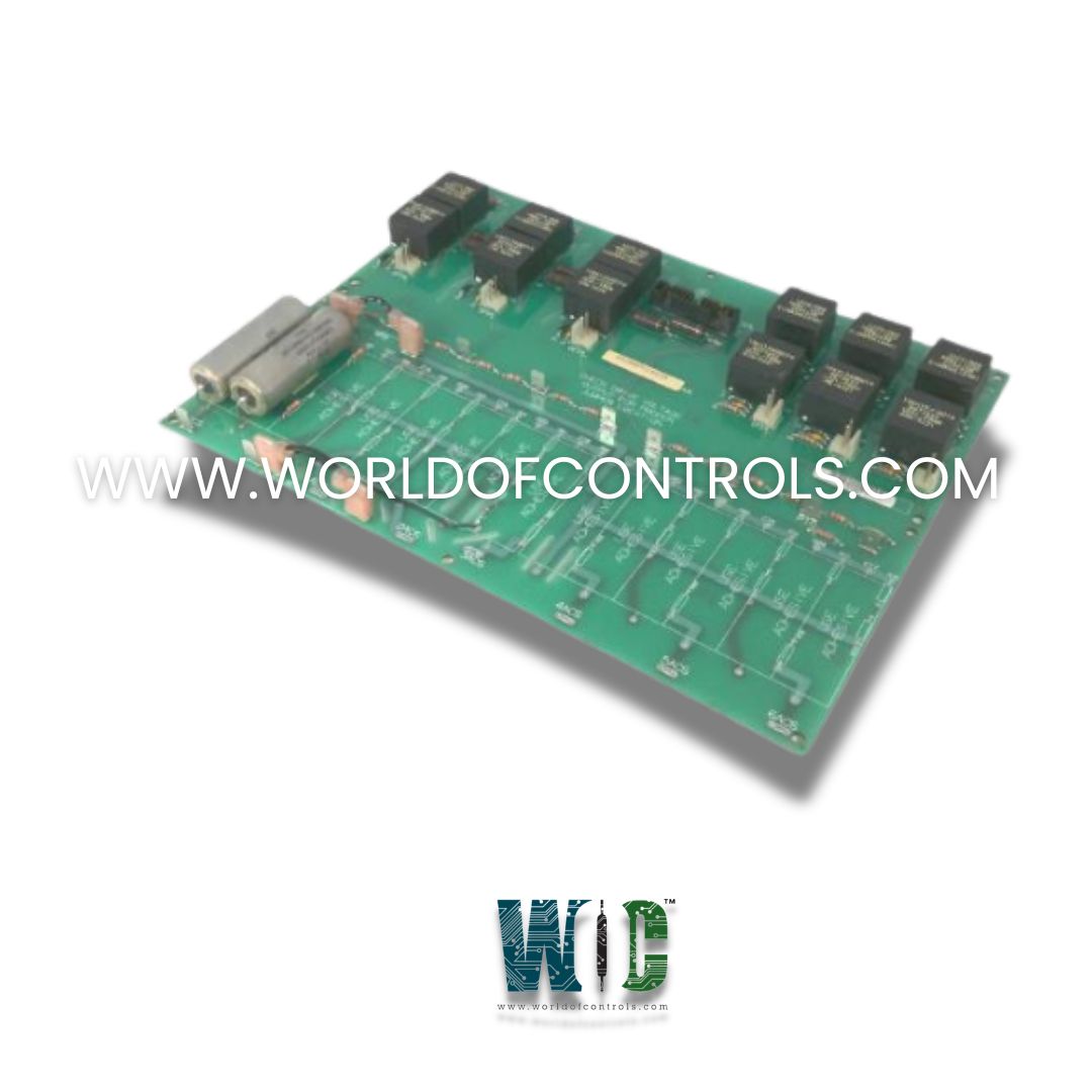
Part No.: DS200PCCAG3A
Manufacturer: General Electric
Country of Manufacture: United States of America (USA)
Product Type: Power Connect Card
Availability: In Stock
Series: EX2000
Functional Description
DS200PCCAG3A is a Power Connect Card developed by GE. It is a part of EX2000 excitation system.This board plays a critical role in linking the system’s control circuitry to the SCR (Silicon Controlled Rectifier) power bridge, acting as a bridge interface that transmits gate signals and voltage feedback. It ensures that controlled gate firing signals are delivered accurately and reliably to the power bridge, which is responsible for regulating power to the excitation system.
Features
- The primary function of the board is to provide gate drive signals to the SCR bridge. This is achieved through the use of pulse transformers, which electrically isolate the control system from the high-voltage SCR components while transmitting the required gate pulses for conduction control. The board manages both forward and reverse gate signals, supporting bidirectional control of the SCRs in the excitation converter.
- In low-to-medium horsepower applications, the board also incorporates snubber circuits—networks of resistors and capacitors that mitigate voltage spikes. These spikes can occur across AC input lines, DC buses, and gate drivers due to rapid switching or inductive load transients. By absorbing and dissipating these spikes, snubber circuits protect sensitive power electronics and contribute to overall system stability.
- For higher horsepower systems, the energy levels involved often require external snubber circuits that are rated for larger currents or voltages. In such configurations, the PCCA board may have partial or no onboard snubber circuits, with these protective elements installed externally elsewhere in the system.
Configurable Jumpers (JP and WP)
Includes four configurable wire jumpers, labeled JP1, JP2, WP3, and WP4. These jumpers are essential for tailoring the board’s operation to match specific system voltages and card group numbers:
- JP1 and JP2 must be connected to designated stab terminals (P3–P10). The exact terminals used depend on the group number of the PCCA board and the system’s input voltage. These connections determine how the pulse transformers and gate drivers are mapped to the SCR bridge.
- WP3 and WP4 are used to bridge terminals P2A to P2B, and P1A to P1B, respectively. These jumpers allow users to configure how the snubber capacitors are connected, specifically determining whether they share the same electrical reference point as the voltage feedback channel. This configuration helps in maintaining coordinated signal referencing and spike suppression.
- Correct jumper placement is crucial for proper board behavior, and layout diagrams and configuration tables are used to guide the installation technician during system setup.
Connectors and Signal Routing
- 1RPL through 6RPL: These six connectors carry reverse gate pulse signals to the respective SCRs on the power bridge.
- 1FPL through 6FPL: These six connectors carry forward gate pulse signals.
- 5PL: This connector is used for interfacing with the power supply board, allowing synchronization and coordination of gate pulses with the system’s overall power logic.
The WOC team is always available to help you with your EX2000 requirements. For more information, please contact WOC.
Frequently Asked Questions
What is DS200PCCAG3A?
It is a Power Connect Card developed by GE under the EX2000 series.
What is an SCR bridge, and how does the PCCA board interact with it?
An SCR bridge controls power flow in the excitation system. The PCCA board provides forward and reverse gate pulses to trigger the SCRs, enabling controlled rectification of AC to DC for generator excitation.
Are snubber circuits included on all boards?
No. Snubber circuits are included on PCCA boards used in low-to-medium horsepower controllers. For higher horsepower systems, external snubber components are used instead, and the PCCA board may have none or partial snubber circuitry.
