SPECIFICATIONS
Part Number: DS200MBHAG2A
Manufacturer: General Electric
Instruction Manual GEI-100172
Series: Drive Control
Function: Multi-bridge Hub Communications Card
Product type: PCB
Abbreviation: MBHA
Board Group Group: 2
Board Hardware: 22 TP, 17 FOConnector, 2 TB, and a Stab Connector
Number of Fiber-Optic Receiver/Transmitter Circuit Pairs: 7
Power Supply Unregulated: 24 VDC
Country of Manufacture: United States (USA)
Functional Description
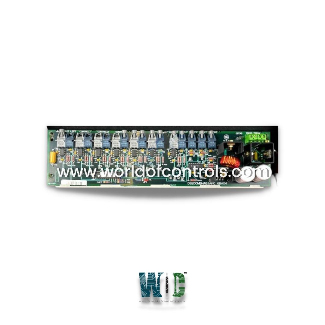
DS200MBHAG2A is a multi-bridge hub communications card developed by GE. It is a part of Drive Control system. This module facilitates fiber optic communication links, enhancing connectivity for the drive it is paired with. It finds applications across a range of GE series drives and automation machinery, offering seamless communication solutions. It includes an internal -5 V de power supply, seven fiber-optic data links consisting of receiver-transmitter pairs, optically coupled logic inputs for control of local broadcast modes, and a programmable logic device to provide system logic.
Features
- The Fiber Optic Communication Links integrated into the module stand as a pivotal feature, comprising seven high-speed (1 Mbaud) fiber optic data links running along the module's edge. These receiver/transmitter pairs serve as critical conduits for seamless and high-bandwidth data exchange, establishing robust communication pathways between diverse components and systems within the setup. This high-speed communication capability ensures rapid and reliable data transmission, supporting efficient coordination and synchronization among interconnected devices.
- The Local and Broadcast Control functionality adds a layer of versatility to the module by offering three fiber optic logic inputs. These inputs enable control over both local and broadcast modes for the drive, providing a flexible and adaptable approach to managing the communication module. Such dynamic control options cater to varying operational demands, allowing for precise management and coordination in different scenarios.
- An Integrated Logic Control System embedded within the module enhances its autonomy and operational efficiency. This system enables the module to execute predefined logic and control functions without continuous manual intervention, thereby reducing reliance on constant user oversight. This feature streamlines operations and improves reliability by automating processes and responses based on predefined parameters and conditions.
- The inclusion of 22 test points within the module serves as a valuable asset for users and maintenance personnel. These test points facilitate the assessment of signal status, board commons, and power supply, offering insights into the system's health and functionality. This comprehensive diagnostic capability aids in troubleshooting and maintenance, ensuring swift identification and resolution of issues for uninterrupted operation.
- The module's compatibility with a wide power supply range, spanning from 15 to 30 VDC, showcases its adaptability to varying operational environments and power sources. This flexibility allows the module to function effectively across different setups, accommodating fluctuations in power input and ensuring stable performance even under diverse operating conditions.
- It encompass cutting-edge fiber optic communication capabilities, versatile control options, an integrated logic control system for autonomous operation, comprehensive test points for diagnostics, and a flexible power supply range. These features collectively contribute to the module's reliability, adaptability, and efficiency in facilitating seamless communication and control within complex industrial setups.
Power Supply
- The power supply for the communication module is housed separately and can be connected to either the lower right or left of the main control chassis. This design ensures efficient power distribution and management, contributing to the overall reliability of the system.
- The power supply chassis features redundant power supplies, adding an extra layer of resilience. This redundancy helps mitigate the impact of power supply failures, maintaining system stability and minimizing disruptions.
Installation and Support
- For proper installation and operation, it's essential to adhere to the manufacturer-provided installation parameters, as well as follow guidelines provided for the associated drive. These measures ensure the system functions optimally and reliably.
- The module comes with a comprehensive manual, the GE Industrial Control Systems Multi-Bridge Hub Communications Board Manual - Manual GEI-100172, offering detailed information about its features, installation, testing, and maintenance. The manual provides a valuable resource for users looking to maximize the capabilities of the module.
Board Groups
- Within the MBHA board, three distinct groups are available, with the G2 group.
- This group's JP1 jumper serves various functions, including normal operations and special settings for factory board resets. Detailed jumper configurations can be found in Table One of the GEI-100172A MBHA Multi-Bridge Hub Communications Board Instruction Guide.
Test Points
- The board incorporates twenty-two test points, each with a unique description.
- For instance, TP13 is responsible for transmitting signals to the fourth bridge of the board. These test points are strategically located within the middle and along the bottom half of the MBHA board, allowing for easy testing and diagnostics.
WOC is happy to assist you with any of your GE requirements. Please contact us by phone or email for pricing and availability on any parts and repairs.
FREQUENTLY ASKED QUESTIONS
What is DS200MBHAG2A?
It is a multi-bridge hub communications card developed by GE under Drive Control system.
What is testpoint TP4 on the module?
Testpoint TP4 on the module is the programmable logic device testpoint oscillator.
How are the fiber-optic transmitter/receiver pairs configured?
It has seven 1 Mbaud fiber-optic data links grouped in transmitter (gray) and receiver (blue) pairs along one edge of the board. These pairs are accessed via duplex fiber-optic cables and receive mode control information from individual drives.
How does the module receive power supply inputs?
It receives power supply inputs through two terminal board connectors: TBPSA and TBPSB. It also features an internal +5 VDC power supply, functioning as a 100 kHz switching power supply.
