SPECIFICATIONS
Part No.: DS200LRPAG2B
Manufacturer: General Electric
Country of Manufacture: United States of America (USA)
Product Type: Line Protection Board
Availability: In Stock
Series: Mark V
Functional Description
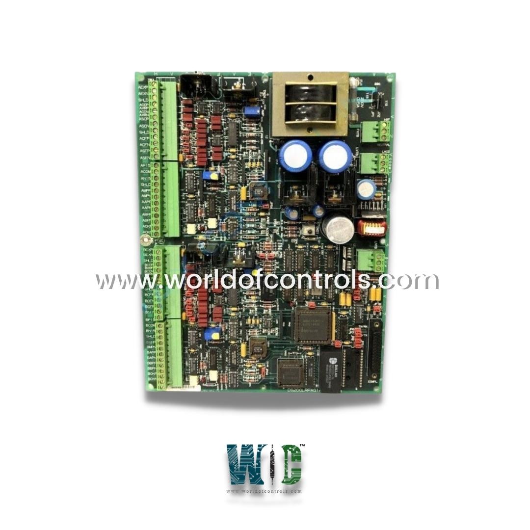
DS200LRPAG2B is a Line Protection Board developed by GE. It is a part of Mark V control system. It works by monitoring electrical parameters and responding rapidly to fault conditions such as short circuits, overloads, and ground faults. By leveraging a combination of relay logic, sensing components, and intelligent decision-making algorithms, helps prevent equipment damage and reduces downtime in the electrical grid.
Features and Capabilities
- Fault Detection and Isolation: The board is equipped to detect a wide range of fault conditions. Upon detecting an abnormality, it sends control signals to circuit breakers to isolate the faulted section. This targeted disconnection prevents the propagation of the fault, allowing unaffected parts of the system to continue operating.
- Overcurrent Protection: An essential protective mechanism is overcurrent protection. The board continuously monitors the current flow in the system, and if it exceeds predefined thresholds, it initiates a trip command to open the circuit. This protects downstream equipment from thermal and mechanical damage due to excessive current.
- Distance Protection: The board supports distance (impedance-based) protection, which is commonly used in high-voltage transmission systems. It measures the impedance between the monitoring point and the fault location. A sudden change in impedance typically indicates a fault, and this method allows the board to determine the location of the fault and respond accordingly.
- Directional Protection: To ensure selective fault clearance, the board incorporates directional protection. This function identifies the direction of the fault current and ensures that only the affected section is isolated, avoiding unnecessary tripping of upstream or adjacent lines.
- Differential Protection: The differential protection feature compares current measurements from both ends of a protected line. If a difference is detected—indicating that current is leaking or being diverted within the line—it quickly triggers isolation. This method is highly sensitive to internal faults and provides fast, accurate protection.
Components
- Transistors mounted to heat sinks: Aid in heat dissipation and ensure efficient performance.
- Jumper switches: Allow for configuration and setting adjustments.
- Relays: Facilitate electrical switching for different control and protection operations.
- Potentiometers: Enable fine-tuning of electrical parameters.
- Integrated circuits (ICs): Provide advanced logic and signal processing capabilities.
- Diodes and resistors: Ensure proper electrical flow and voltage regulation.
- Vertical female cable connector: Supports seamless connectivity with other system components.
- Stab-on connectors: Offer quick and secure electrical connections.
- Two terminal strips: Provide wiring terminals for easy integration into the control system.
- LED indicators: Offer visual status updates and diagnostics.
- Reset switch: Allows for manual resetting of the board.
- Transformer component: Manages voltage transformation for stable operation.
Installation and Maintenance Considerations
- Proper installation and routine maintenance are essential for ensuring the long-term reliability and performance of the Line Protection Board. Adequate ventilation must be provided within the control cabinet to prevent thermal buildup, especially since the board relies on heat sinks to dissipate excess heat generated by high-power components such as transistors. Overheating can lead to component degradation or operational faults, so maintaining airflow and keeping ambient temperatures within specified limits is critical.
- During operation, the LED indicators on the board should be routinely inspected to monitor system status and diagnose potential issues. These visual indicators provide immediate feedback on fault conditions, communication activity, and power status, aiding in quick identification of abnormal events.
- The jumper switches and potentiometers on the board should be used carefully during initial configuration and any subsequent recalibration. These components allow for fine-tuning of protection parameters, such as trip thresholds or time delays, and should be adjusted according to system requirements and manufacturer guidelines.
- Finally, it is important to ensure that all cable connections, including those using vertical female connectors and stab-on terminals, are securely fastened. Loose or improperly seated connections can lead to intermittent faults, data loss, or inaccurate readings, which can compromise the board’s protective functions. Periodic inspection and tightening of connections, as well as verifying the integrity of terminal strips, help maintain consistent performance and reduce the risk of unplanned downtime.
The WOC team is always available to help you with your Mark V requirements. For more information, please contact WOC.
Frequently Asked Questions
What is DS200LRPAG2B?
It is a Line Protection Board developed by GE under the Mark V series.
How do I install the board?
Ensure the power is disconnected before installation. Securely connect cables and connectors to the appropriate ports. Configure the jumper switches according to the system requirements. Verify the LED indicators for correct operation after powering up.
How do I troubleshoot the board?
Check LED indicators for error signals. Inspect connectors and terminal strips for loose wiring. Use a multimeter to test voltage levels. Reset the board using the reset switch if needed. Consult the Mark V system manual for detailed error codes.
