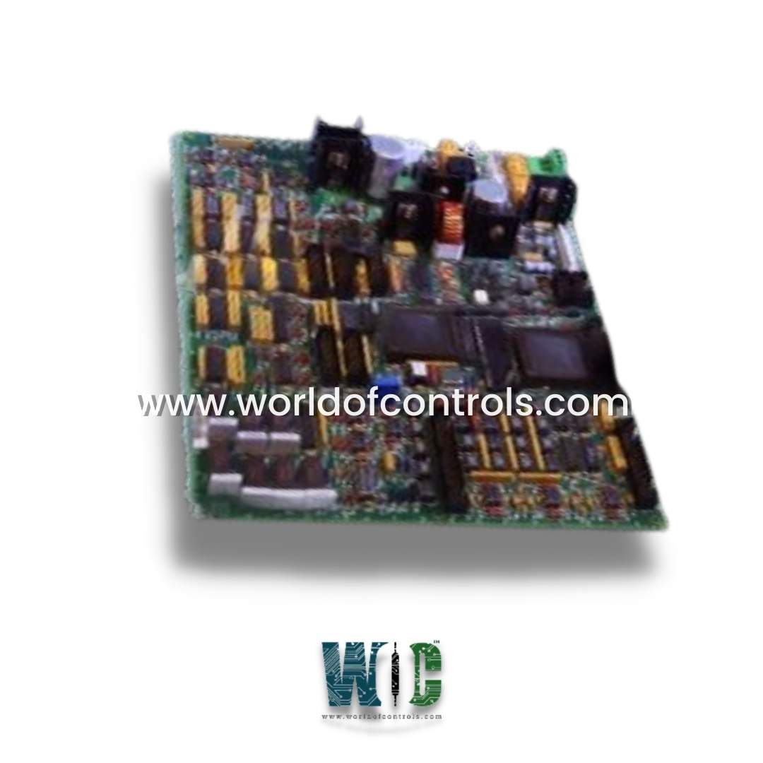
World Of Controls understands the criticality of your requirement and works towards reducing the lead time as much as possible.
DS200GGIAG1B - GTO AC2000 Bridge Interface Board is available in stock which ships the same day.
DS200GGIAG1B - GTO AC2000 Bridge Interface Board comes in UNUSED as well as REBUILT condition.
To avail our best deals for DS200GGIAG1B - GTO AC2000 Bridge Interface Board, contact us and we will get back to you within 24 hours.
SPECIFICATIONS:
Part Number: DS200GGIAG1B
Manufacturer: General Electric
Series: EX2000
Product Type: GTO AC2000 Bridge Interface Board
Power Requirements: +5 V dc, 6 A
Number of relay channels: 12
Power supply voltage: 28 V dc
Mounting: DIN-rail mounting
Technology: Surface mount
Operating temperature: -30 to +65°C
Size: 15.9 cm high x 17.8 cm
Repair: 3-7 Day
Availability: In Stock
Country of Origin: United States
Manual: GEH-6120B
FUNCTIONAL DESCRIPTION:
DS200GGIAG1B is a GTO AC2000 Bridge Interface Board manufactured and designed by General Electric as part of the EX2000 Series used in GE Excitation Control Systems. It is used to interface between the control system and the turbine's AC power system. The AC Bridge Card may be used to monitor and control the voltage, current, frequency, and other parameters of the AC power system to ensure that the turbine is operating within safe and optimal conditions. It may also provide real-time feedback to the control system about the performance of the turbine and the AC power system. Communication can be configured with redundant levels to provide modular backups. The product is pre-drilled along each edge and corner for the installation of hardware such as standoffs and screws. It is a large board with many components, including ten male cable connectors ranging in size from 12-pin to 40-pin. They are all vertical pin connectors. Six vertical pin header connectors, stab-on connectors, and two small (3-position) terminal strips are provided on the board.
FEATURES:
WOC has the largest stock of GE Excitation Control System Replacement Parts. We can also repair your faulty boards. WORLD OF CONTROLS can also supply unused and rebuilt backed-up with a warranty. Our team of experts is available round the clock to support your OEM needs. Our team of experts at WOC is happy to assist you with any of your automation requirements. For pricing and availability on any parts and repairs, kindly get in touch with our team by phone or email.
What is the AC2000 Bridge Interface Board, and what is its primary function?
The AC2000 Bridge Interface Board is a device that serves as a communication interface between different systems or devices, facilitating seamless data exchange.
Which communication protocols does the AC2000 Bridge Interface Board support?
The board supports a range of communication protocols, including RS-232, RS-485, Modbus, and Ethernet/IP, ensuring compatibility with various systems.
What types of inputs and outputs does the AC2000 Bridge Interface Board have?
The board features both digital and analog input/output ports to accommodate different types of sensors, actuators, and other devices.