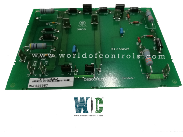
World Of Controls understands the criticality of your requirement and works towards reducing the lead time as much as possible.
DS200FECBG1A - Field Exciter Control Board is available in stock which ships the same day.
DS200FECBG1A - Field Exciter Control Board comes in UNUSED as well as REBUILT condition.
To avail our best deals for DS200FECBG1A - Field Exciter Control Board, contact us and we will get back to you within 24 hours.
SPECIFICATIONS:
Part No: DS200FECBG1A
Manufacturer: General Electric
Function: Field Excitation Control for Synchronous Generator
Series: EX200
Input Signal Type: Analog voltage and current reference signals
Exciter Connector Type: 34
Terminal Block: 12
Power Supplies: 240 Vdc
Input Voltage Range: ±10 V DC
Output Current Range: 0 – 5 A
Output Voltage: 0 – 120 V DC
Operating Temperature: 0°C to 70°C
Mounting: DIN rail
Availability: In Stock
Weight: 2.00 lbs
Size: 9.2 x 6.5 inches
Country of Origin: USA
Manual: GEI-100195
FUNCTIONAL DESCRIPTION:
DS200FECBG1A is a Field Exciter Control Board manufactured and designed by General Electric and is part of the EX200 Series used in GE Excitation Turbine Control systems. The board receives reference signals from the EX2000 system and converts them into a regulated DC excitation current applied to the generator’s rotor windings. It maintains generator terminal voltage within tight tolerances, supports power factor control, and responds to transient load changes. The FECB includes analog and digital signal conditioning circuits, opto-isolated interfaces, and precision voltage and current sensing, ensuring accurate signal transmission and isolation between the control system and high-power excitation circuitry.
The board also integrates protective and diagnostic features critical for generator and system safety. Overvoltage, overcurrent, and short-circuit detection circuits monitor the excitation output and trigger alarms or trips in abnormal conditions. The module supports dynamic response during load swings or grid disturbances, providing fast corrective action to stabilize generator output. Additionally, onboard diagnostics provide continuous monitoring of excitation components, relay status, and fault conditions, transmitting real-time feedback to the EX2000 control system for predictive maintenance and fault mitigation. The combination of precise regulation, robust protection, and adaptive response makes the FECB essential for reliable and efficient generator operation.
INSTALLATION:
The Field Exciter Control Board should be installed in the designated I/O rack or module slot of the EX2000 Excitation Control System, ensuring correct orientation and secure mechanical mounting. Before installation, verify that all power sources to the control system and generator excitation circuits are completely de-energized to prevent electrical hazards. The board is designed for hot-swappable compatibility only if specified, but standard practice is to install it with the system powered down.
Electrical connections must follow the EX2000 wiring diagrams precisely. Input control signals from the EX2000 system, including voltage and current references, should be connected to the designated terminals, ensuring proper polarity and grounding. The excitation output terminals should be connected to the generator field windings via appropriate cabling, maintaining low impedance and avoiding routing near high-power AC lines to prevent noise interference. After installation, verify all jumpers and configuration settings (if applicable) for the specific generator and system requirements. Perform a system checkout by gradually energizing the excitation circuits while monitoring voltages, currents, and protective interlocks to confirm correct operation and ensure no faults are present.
OPERATIONS:
The board receives analog voltage and current reference signals from the EX2000 excitation regulator via isolated input terminals. These references are processed through precision DACs and conditioning circuitry to generate a regulated DC excitation output. The board employs a closed-loop control topology, continuously comparing the actual generator field current with the reference signal to adjust the excitation drive through high-speed power amplifiers.
Excitation output is monitored via integrated voltage and current sensors. Overvoltage, overcurrent, and short-circuit conditions are detected by dedicated protection comparators; faults trigger the EX2000 system interlocks to isolate the excitation output and generate diagnostic alarms. The board also supports dynamic response compensation, using fast signal conditioning and feedback loops to maintain stability under load transients, step changes, and grid disturbances. Status signals from onboard relays and sensing circuits are transmitted to the EX2000 system for real-time diagnostics, predictive maintenance, and performance logging.
WOC maintains the largest inventory of Replacement parts for GE Excitation Turbine Control systems. Additionally, we offer warranty-backed unused and rebuilt boards as well as board repairs for your damaged ones. For your OEM needs, our team of professionals is available around the clock. We at WOC are happy to help you with any needs you may have in terms of automation. Please contact our team by phone or email for pricing and availability on any components and repairs.
What is the primary function of the Field Exciter Board?
The board precisely regulates the generator’s field current by converting reference signals from the EX2000 Excitation Control System into a controlled DC output. It maintains terminal voltage and power factor within tight tolerances under varying load conditions. The closed-loop control continuously monitors field current and adjusts excitation dynamically to ensure stable generator operation.
What types of input signals does the board process?
The board accepts analog voltage and current reference signals, typically ±10 V DC, from the EX2000 controller. These inputs pass through isolation and signal conditioning circuits to prevent interference and maintain accuracy. The conditioned signals are then processed by high-speed DACs and control loops to generate precise excitation output.
How does the board control the excitation output?
Excitation output is controlled using a closed-loop feedback mechanism that compares actual field current to the reference signal. High-speed power amplifiers adjust the DC output in real time to match the desired setpoint. This ensures rapid response to load changes, grid disturbances, and transient conditions while maintaining system stability.