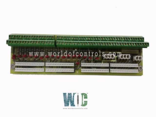
World Of Controls understands the criticality of your requirement and works towards reducing the lead time as much as possible.
DS200DTBDG1ABA - Contact Output Expansion Termination Module is available in stock which ships the same day.
DS200DTBDG1ABA - Contact Output Expansion Termination Module comes in UNUSED as well as REBUILT condition.
To avail our best deals for DS200DTBDG1ABA - Contact Output Expansion Termination Module, contact us and we will get back to you within 24 hours.
SPECIFICATIONS:
Part Number: DS200DTBDG1ABA
Manufacturer: General Electric
Series: Mark V
Module Type: Contact Output Expansion Termination Module
Relay Signal Inputs: 8
Relay Signal Source: TCRA board
Total Output Channels: 30
Solenoid Output Configuration: Up to 16 outputs
Solenoid Power Supply: 125 V DC
Solenoid Power Connector: J8
Ignition Transformer Power: 125 V DC
Ignition Power Connectors: J19 and J20
Size: 8.25 cm high x 4.18 cm
Repair: 3-7 Days
Availability: In Stock
Weight: 2.5 Kg
Country of Origin: United States
FUNCTIONAL DESCRIPTION:
DS200DTBDG1ABA is a Contact Output Expansion Termination Module manufactured and designed by General Electric as part of the Mark V Series used in GE Speedtronic Gas Turbine Control Systems. The Contact Output Expansion Termination Module (DTBD) is installed in cabinets Q11, Q21, and Q51. This module interfaces with the 30 relays present on the Terminal Contact Relay Assembly (TCRA), which is located in position five of each of these cabinets. The DTBD plays a critical role in managing output signals, facilitating connections between control signals and field devices.
The DTBD located in position four of cabinets Q21 and Q51 supports flexible configuration options. Sixteen of its 30 outputs can be designated for solenoid operation by setting specific hardware jumpers on the module. Additionally, two of the contact outputs, specifically outputs #47 and #48, can be repurposed for ignition transformers. This is made possible by connecting jumpers J19 and J20, and simultaneously removing the factory-installed wire jumpers. This setup allows the DTBD to provide tailored output configurations based on system requirements.
INSTALLATION:
The DTBD should be installed in designated panel locations, typically in slots within cabinets Q11, Q21, and Q51, as per system design documentation. Carefully align the module with the mounting rails and secure it using appropriate fasteners. Ensure that all field wiring and internal connections are routed neatly and according to wiring diagrams. Use proper cable markers and verify that the terminal screws are tightened to manufacturer-recommended torque settings to avoid loose connections.
Once mounted, connect the DTBD to the corresponding Terminal Contact Relay Assembly (TCRA), typically located in position five of the same cabinet. If solenoid outputs are required, configure the designated 16 output channels using the hardware jumpers provided on the DTBD. For ignition transformer outputs (#47 and #48), ensure jumpers J19 and J20 are connected and remove the factory-installed wire jumpers. Double-check all connections and jumper settings before powering up the system to ensure safe and reliable operation.
OPERATION:
During normal operation, the Contact Output Expansion Termination Module (DTBD) functions as the interface between the turbine control system and field devices, distributing command signals to relays, solenoids, and ignition transformers. It receives control signals via the Terminal Contact Relay Assembly (TCRA) and routes them to the appropriate field output devices based on pre-configured hardware jumper settings. Each of the 30 output channels can operate contact-based devices, with specific channels adaptable for solenoid or ignition transformer use.
The DTBD ensures reliable signal transmission by maintaining electrical isolation and providing consistent voltage levels to connected devices. When solenoid or ignition outputs are enabled, the module ensures that the configured outputs are properly energized in response to control logic from the system. Its modular and hardware-configurable design allows for easy maintenance and adaptability, enabling operators to adjust functionality as needed based on system requirements or operational changes. Regular inspection of jumper settings, wiring integrity, and output performance is recommended to ensure continued reliable operation.
DTBD CONNECTORS:
Connectors JS1 through JS8 on the Contact Output Expansion Termination Module (DTBD) are used to read relay signals directly from the Terminal Contact Relay Assembly (TCRA), which is located in position five of the cabinet. These connectors play a key role in capturing the state of each relay, allowing the DTBD to properly process and forward the corresponding control outputs to the connected field devices.
WOC maintains the largest stock of replacement parts for GE Speedtronic Gas Turbine Control Systems, offering both unused and rebuilt boards with warranty coverage. We also provide expert repair services for damaged units. Our dedicated team of professionals is available around the clock to support all your OEM and automation needs. For pricing and availability of parts or repair services, please contact us by phone or email.
What is the function of the DTBD?
The DTBD acts as an interface module that expands contact outputs from the control system, allowing signals to be routed to relays, solenoids, and ignition transformers in the field. It helps organize and distribute output signals efficiently within the turbine control system.
No signal detected on JS1 through JS8 connectors. What might cause this?
If signals are missing on JS1 through JS8, inspect the wiring from the TCRA board at location five for any loose connections, damage, or disconnections. Additionally, verify that the TCRA board itself is powered on and functioning properly. Check for any blown fuses or faults within the relay assembly that could interrupt signal transmission.
How is power supplied to the solenoid outputs?
Power for the solenoid outputs is provided via connector J8, which receives 125 V DC from the TCPD board located in the PD core. This ensures that solenoid devices connected to the DTBD have the necessary operating voltage.