SPECIFICATIONS
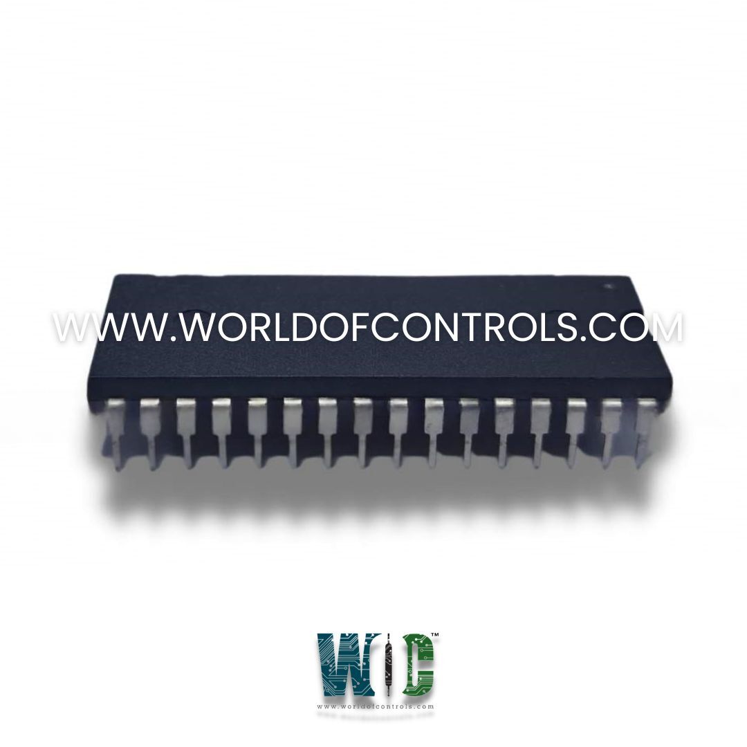
Part No.: DS200DENQF1BDD
Manufacturer: General Electric
Country of Manufacture: United States of America (USA)
Product Type: Software EPROM
Availability: In Stock
Series: Mark V
Functional Description
DS200DENQF1BDD is a Software EPROM developed by GE. It is part of the Mark V series. The EPROM stores the control algorithms and operational parameters that manage turbine operation, ensuring efficiency and safety.his can include manufacturing, chemical processing, and other automated operations requiring precise control and monitoring. It ensures that safety protocols and emergency response routines are properly stored and executed, enhancing the overall safety of industrial operations.
System Operation and Maintenance
- The operator interface of the turbine control system comprises a VGA color graphics monitor, keyboard, and printer, providing operators with essential tools for monitoring and controlling turbine operations. These components collectively enable operators to interact with the system, input commands, and receive critical information regarding the turbine's status, parameters, and alarms. The operator interface offers various functions, as outlined in Table 6, designed to provide operators with comprehensive control and monitoring capabilities over turbine operations.
- The central display on the operator interface is the unit control display, presenting the status of major selections and key turbine parameters in a structured table format. This display includes essential information such as variable names, current values, and engineering units. Additionally, it lists the oldest three unacknowledged alarms, ensuring operators stay informed about any potential issues. Furthermore, the operator interface supports a user-defined display feature, allowing operators to create custom variable lists tailored to their specific monitoring needs. Operators can manually input turbine-generator variables of interest, which are then added to the variable list for easy access and monitoring.
- Commands that initiate changes in the turbine's state, such as start or stop commands, require an arm-activate sequence to prevent accidental operation. However, setpoint incrementing commands are processed immediately and do not necessitate an arm-activate sequence, streamlining certain operational tasks. To ensure optimal performance and reliability, regular maintenance of the operator interface is essential. This includes routine inspections, cleaning, and keeping the system software up to date with the latest patches and enhancements.
- Proper training of operators is crucial for effective utilization of the operator interface. Operators should be trained on system navigation, familiarizing them with the interface layout, menu options, and navigation procedures. Additionally, operators must understand the importance of following command execution protocols, such as the arm-activate sequence, to prevent accidental or unauthorized operation of the turbine. By adhering to proper operation and maintenance procedures and providing comprehensive training to operators, turbine control systems can ensure the operator interface remains reliable and effective in facilitating safe and efficient turbine operation.
System Control Configuration
- At the heart of this intricate system lie three identical controllers, denoted as R, S, and T, each playing a pivotal role in executing critical control algorithms, protective functions, and sequencing within the system's operations. These processors serve as the nerve center, orchestrating the entire array of control strategies while simultaneously acquiring essential data and generating outputs vital for regulating the turbine's operation.
- The fundamental responsibility of R, S, and T involves the execution of crucial control algorithms and protective functions. These processors meticulously handle the sequencing of operations and actively engage in data acquisition, gathering the necessary information required for optimal performance. Furthermore, they generate outputs that directly influence and regulate the functioning of the turbine.
- The system prioritizes safety measures by routing protective outputs through the P module, which comprises triple redundant processors X, Y, and Z. These processors within the P module operate independently and provide additional layers of protection, particularly for critical functions such as overspeed regulation.
- Additionally, the three control processors R, S, and T acquire data from a series of triple-redundant sensors. Simultaneously, they retrieve information from dual or single sensors, thereby ensuring comprehensive data collection.
- It's important to note that all sensors crucial for continuous controls and protection are designed with triple redundancy, reinforcing the system's reliability and safety.
- However, other sensors, serving supplementary functions, may consist of dual or single devices distributed among the three control processors.
The WOC team is always available to help you with your Mark V requirements. For more information, please contact WOC.
Frequently Asked Questions
What is DS200DENQF1BDD?
It is a Software EPROM developed by GE under the Mark V series.
What components make up the operator interface of the turbine control system?
The operator interface consists of a VGA color graphics monitor, keyboard, and printer, providing operators with essential tools for monitoring and controlling turbine operations.
What functions are available on the operator interface?
The operator interface offers various functions, including displaying turbine status and parameters, presenting alarms, and allowing operators to input commands and create custom variable lists.
What is the purpose of the unit control display on the operator interface?
The unit control display presents the status of major selections, key turbine parameters, and unacknowledged alarms in a structured table format, ensuring operators stay informed about the turbine's operational status.
