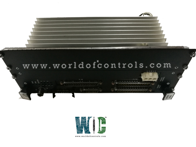
World Of Controls understands the criticality of your requirement and works towards reducing the lead time as much as possible.
IS215VPROH2B - Turbine Protection Board is available in stock which ships the same day.
IS215VPROH2B - Turbine Protection Board comes in UNUSED as well as REBUILT condition.
To avail our best deals for IS215VPROH2B - Turbine Protection Board, contact us and we will get back to you within 24 hours.
SPECIFICATIONS:
Part No: IS215VPROH2B
Manufacturer: General Electric
Function: Turbine Protection Board
Series: Mark VI
Number of Inputs: 3
Number of Outputs: 6
Operating temperature: -30 to 65 ºC
Power Supply Voltage: 125 V dc
Technology: Surface Mount
Board Size: 33.0 cm high x 17.8 cm
Availability: In Stock
Country of Origin: USA
Manual: GEH-6421H
FUNCTIONAL DESCRIPTION:
IS215VPROH2B is a Turbine Protection Board manufactured and designed by General Electric as part of the Mark VI Series used in GE Speedtronic gas turbine control systems. The Turbine Protection Board (VPRO) and associated terminal boards (TPRO and TREG) provide an independent emergency overspeed protection system. The protection system consists of triple redundant VPRO boards in a module separate from the turbine control system, controlling the trip solenoids through TREG.
The VPRO board in the Protection Module
provides the emergency trip function. Up to three trip solenoids can be connected between the TREG and TRPG terminal boards. TREG provides the positive side of the 125 V dc to the solenoids and TRPG provides the negative side. Either board can trip the turbine. VPRO provides emergency overspeed protection and emergency stop functions. It controls the 12 relays on TREG, nine of which form three groups of three to vote inputs controlling the three trip solenoids. A second TREG board may be driven from VPRO through J4.
INSTALLATION:
OPERATION:
The main purpose of the protection module is emergency overspeed (EOS) protection for the turbine, using three VPRO boards. In addition, VPRO has backup synchronization check protection, three analog current inputs, and nine thermocouple inputs, primarily intended for exhaust over-temperature protection on gas turbines.
The protection module is always triple redundant with three completely separate and independent VPRO boards named R8, S8, and T8 (originally named X, Y, and Z). Any one of these boards can be powered down and replaced while the turbine is running without jeopardizing the protection system. Each board contains its own I/O controller. The communications allow the initiation of test commands from the controller to the protection module and the monitoring of EOS system diagnostics in the controller and on the operator interface. Communications are resident on the VPRO board, which is the heart of the system. The VPRO board has a VME interface to allow programming and testing in a VME rack; however, the backplane is neutralized when plugged into the protection module to eliminate any continuity between the three independent sections.
SPEED CONTROL AND OVERSPEED PROTECTION:
Speed control and overspeed protection are implemented with six passive, magnetic speed pickups. The first three are monitored by the controllers, which use the median signal for speed control and primary overspeed protection. The second three are separately connected to the R8, S8, and T8 VPROs in the protection module. Provision is made for nine passive magnetic speed pickups or active pulse rate transducers (TTL type) on the TPRO terminal board with three being monitored by each of the R8, S8, and T8 VPROs. Separate overspeed trip settings are programmed into the application software for the primary and emergency overspeed trip limits, and a second emergency overspeed trip limit must be programmed into the I/O configurator to confirm the EOS trip point.
POWER SUPPLY:
There is an on-board power supply on each VPRO board. Using 125 V dc from the cabinet PDM, this produces 5 V and 28 V. Therefore, for great dependability, the complete protection module contains three power supplies. The J2 power cable and the trip solenoids are the only connections to the control modules since VPRO is solely in charge of controlling TREG. When a turbine trips in simplex systems, a third cable transmits a trip signal from J1 to the TSVO terminal board, which operates a servo valve clamp.
WOC maintains the largest inventory of replacement parts for GE Speedtronic control systems. Additionally, we offer warranty-backed unused and rebuilt boards as well as board repairs for your damaged ones. For your OEM needs, our team of professionals is available around the clock. We at WOC are happy to help you with any needs you may have in terms of automation. Please contact our team by phone or email for pricing and availability on any components and repairs.
Why is a Turbine Protection Board important?
A Turbine Protection Board is crucial for safeguarding the turbine equipment from potential damage due to overloading, overheating, excessive vibration, or other adverse conditions. It helps in maintaining the reliability, efficiency, and longevity of the turbine system while ensuring the safety of personnel and surrounding infrastructure.
What are the common features of a Turbine Protection Board?
Typical features of a Turbine Protection Board include real-time monitoring, alarm generation, fault diagnostics, trip logic programming, communication interfaces for data exchange, and integration with the overall control system of the power plant or industrial facility.
How does a Turbine Protection Board work?
The Turbine Protection Board continuously monitors the relevant parameters using sensors installed at strategic locations within the turbine system. It compares the measured values against pre-set thresholds or operating limits. If any parameter exceeds the allowed range, the protection board initiates appropriate actions, such as shutting down the turbine or activating alarms.