World Of Controls understands the criticality of your requirement and works towards reducing the lead time as much as possible.
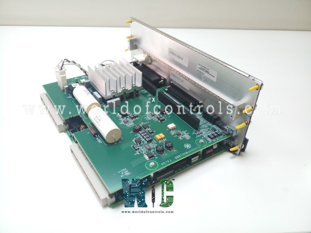
IS215VPROH1BH - Turbine Protection Board is available in stock which ships the same day.
IS215VPROH1BH - Turbine Protection Board comes in UNUSED as well as REBUILT condition.
To avail our best deals for IS215VPROH1BH - Turbine Protection Board, contact us and we will get back to you within 24 hours.
SPECIFICATIONS:
Part Number: IS215VPROH1BH
Manufacturer: General Electric
Series: Mark VI
Product Type: Turbine Protection Board
Number of Inputs: 4 - 20 mA
Number of Outputs: 6
Power Supply Voltage: 125 V DC
Thermocouple types: E, J, K, S, T
Span: -8 mV to +45 mV
Common Mode Voltage Range: ±5 V
Dimensions: 16.51 cm High x 17.8 cm
Operating temperature: 30 to 60 °C
No.of Analog Voltage Inputs: 6
Repair: 3-7 days
Availability: In Stock
Country of Origin: United States
Manual: GEH-6721H
FUNCTIONAL DESCRIPTION:
IS215VPROH1BH is a Turbine Protection Board manufactured and designed by General Electric as part of the VI Series used in GE Speedtronic Control Systems. The Turbine Protection Board (VPRO) and associated terminal boards (TPRO and TREG) provide an independent emergency overspeed protection system. The protection system consists of triple-redundant VPRO boards in a module separate from the turbine control system, controlling the trip solenoids through TREG. The VPRO board in the Protection Module P provides the emergency trip function. Up to three trip solenoids can be connected between the TREG and TRPG terminal boards. TREG provides the positive side of the 125 V DC to the solenoids, and TRPG provides the negative side. Either board can trip the turbine. VPRO provides emergency overspeed protection and emergency stop functions. It controls the 12 relays on TREG, nine of which form three groups of three to vote inputs controlling the three trip solenoids. A second TREG board may be driven from VPRO through J4.
INSTALLATION:
OPERATION:
The VPRO board’s primary function is to provide Emergency Overspeed System (EOS) protection through a triple-redundant setup. It also offers:
Each VPRO board has its own I/O controller and communicates with the turbine controller to execute test commands and monitor diagnostics. The VME interface allows programming and testing, while the backplane is neutralized in protection mode to maintain isolation between R8, S8, and T8.
INTERFACE TO TRIP SOLENOIDS:
The trip system combines the Primary Trip Interface from the controller with the EOS Trip Interface from the protection module. Three separate, triple-redundant trip solenoids (also called Electrical Trip Devices - ETDs) are used to interface with the hydraulics. The ETDs are connected between the TRPG and TREG terminal boards. A separately fused 125 V DC feeder is provided from the turbine control for each solenoid, which energizes in the run mode and de-energizes in the trip mode.
WOC has the largest stock of OEM Replacement Parts for GE Speedtronic Control Systems. We can also repair your faulty boards and supply unused and rebuilt boards backed up with a warranty. Our team of experts is available around the clock to support your OEM needs. Our team of experts at WOC is happy to assist you with any of your automation requirements. For pricing and availability on parts and repairs, kindly contact our team by phone or email.
What type of analog inputs and outputs does the IS215VPROH1BH have?
The board features three analog current inputs (4–20 mA), six analog voltage inputs, and six output signals for system control and monitoring. These inputs are used to monitor turbine operating conditions, while outputs interact with connected systems like the TREG board, enabling real-time protection actions.
What thermocouple types are supported by the Turbine Protection Board?
The board supports five standard thermocouple types: E, J, K, S, and T. These are commonly used in industrial applications to monitor exhaust gas temperatures, especially in gas turbines. The input span supported by the board ranges from -8 mV to +45 mV, and the thermocouples help trigger alarms or trips in case of over-temperature conditions that could damage the turbine or related systems.
What is the typical lead time for Turbine Protection Board repairs?
The standard repair lead time ranges from 3 to 7 working days, depending on the board’s condition and the complexity of the repair required. WOC provides thorough diagnostic testing, component-level repair, and functional verification using OEM test setups. Fast-track repairs may be available upon request, depending on urgency and availability