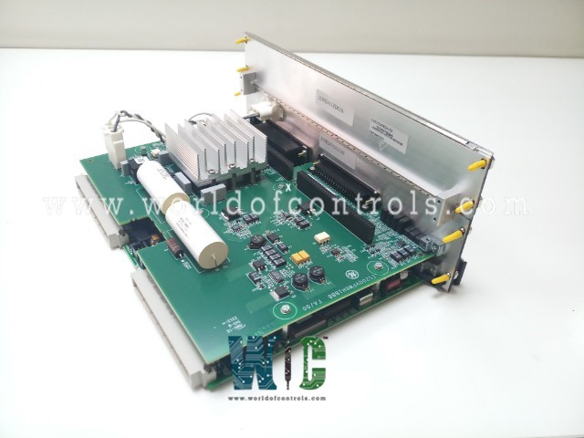
IS215VPROH1BD - Emergency Turbine Protection Module

IS215VPROH1BD - Emergency Turbine Protection Module IS215VPROH1BD - Emergency Turbine Protection Module

World Of Controls understands the criticality of your requirement and works towards reducing the lead time as much as possible.

IS215VPROH1BD - Emergency Turbine Protection Module is available in stock which ships the same day.

IS215VPROH1BD - Emergency Turbine Protection Module comes in UNUSED as well as REBUILT condition.

To avail our best deals for IS215VPROH1BD - Emergency Turbine Protection Module, contact us and we will get back to you within 24 hours.

SPECIFICATIONS

Part No.: IS215VPROH1BD
Manufacturer: General Electric
Country of Manufacture: United States of America (USA)
Frame Rate Up to 100 Hz
MPU Pulse Rate Range 2 Hz to 20 kHz
Input supply: 125 V dc (70-145 V dc)
Output: 5 V dc and 28 V dc
Product Type: Emergency Turbine Protection Module
Availability: In Stock
Series: Mark VI

Functional Description

IS215VPROH1BD is a Emergency Turbine Protection Module developed by GE. It is a part of Mark VI control system. The Emergency Turbine Protection board, along with its associated terminal boards (TPRO and TREG), constitutes a critical component of the emergency overspeed protection system, ensuring the safety and integrity of turbine operations.� The VPRO board, along with the TPRO and TREG terminal boards, establishes an independent emergency overspeed protection system. This system operates redundantly to safeguard against potential overspeed conditions, which pose significant risks to turbine operations and personnel safety.

Features

  • Triple Redundant Configuration: The protection system comprises triple redundant VPRO boards housed in a separate module from the turbine control system. These boards work in tandem to control trip solenoids through the TREG terminal board. This redundant configuration enhances reliability and ensures continuous protection even in the event of component failure or malfunction.
  • Cabling Configuration: Cabling from the TPRO and TREG terminal boards to the VPRO board facilitates seamless communication and coordination within the protection system. Proper cabling ensures efficient transmission of signals and commands between the components, enabling timely response to emergency situations.
  • Ethernet Connectivity: In addition to its primary functions, the VPRO board features an Ethernet connection for IONet communications with the control modules. This connectivity enables data exchange and integration with the broader control network, enhancing monitoring and management capabilities.
  • Emergency Trip Function: The VPRO board, located in the Protection Module, is responsible for executing the emergency trip function. It is capable of tripping the turbine in response to overspeed conditions or other critical events that threaten safe operation. The board ensures swift and decisive action to mitigate risks and prevent potential damage or accidents.
  • Trip Solenoid Configuration: Up to three trip solenoids can be connected between the TREG and TRPG terminal boards. TREG provides the positive side of the 125 V DC power supply to the solenoids, while TRPG provides the negative side. This configuration enables either board to initiate a turbine trip, ensuring redundancy and reliability in emergency shutdown scenarios.
  • Relay Control: Exercises control over the 12 relays on the TREG terminal board. Among these relays, nine are organized into three groups of three, forming a voting mechanism for inputs that govern the operation of the trip solenoids. This arrangement enhances reliability by enabling a consensual decision-making process before initiating critical actions.

MPU Characteristics

  • Output Resistance and Inductance: The MPU possesses an output resistance of 200 ohms coupled with an inductance of 85 mH. These parameters influence the impedance matching and signal transmission capabilities of the MPU, ensuring efficient communication within the system.
  • Output Voltage: At the terminal block, the MPU generates an output voltage of 150 V peak-to-peak (p-p) when connected to a load impedance of 60 K ohms. Despite this voltage level, the energy delivered is insufficient to generate a spark, indicating a safe operating condition.
  • Maximum Short Circuit Current: The MPU is designed to limit the maximum short circuit current to approximately 100 mA. This feature safeguards against excessive current flow in the event of a short circuit, preventing damage to the MPU and associated components.
  • Normal Mode Load: To mitigate voltage levels at the input signal terminals, the system applies a normal mode load of up to 400 ohms. This load serves to reduce the voltage across the terminals, ensuring compatibility with downstream components and preventing overvoltage conditions.

The WOC team is always available to help you with your Mark VI requirements. For more information, please contact WOC.

Frequently Asked Questions

What is IS215VPROH1BD?
It is a high-speed serial-link interface board developed by GE under the Mark VI series.

What is the purpose of the ID device on the TPRO and TREG terminal board connectors?
The ID device serves as a crucial identification component that provides essential information about the terminal board. It includes details such as the serial number, board type, revision number, and plug location.

How does the ID device function?
The ID device is a read-only chip that stores encoded information about the terminal board. When the chip is interrogated by the I/O board, it retrieves this information, enabling the system to identify and verify the terminal board's specifications.

What happens if a mismatch is detected during interrogation?
In the event of a mismatch between the information retrieved from the ID device and the expected specifications, a hardware incompatibility fault is generated. This fault alerts the system to a potential issue, prompting further investigation and resolution.

Why is the ID device important for system integrity?
The ID device plays a crucial role in ensuring system integrity and compatibility. By providing accurate information about the terminal board, it helps prevent compatibility issues and ensures that components are properly matched and configured within the system.