SPECIFICATIONS
Part No.: IS215VCMIH2CBB
Manufacturer: General Electric
Country of Manufacture: United States of America (USA)
Number of channels: 8
Span: 0.3532 to 4.054 V
Maximum lead resistance: 15 ohm
Product Type: Communications Card
Availability: In Stock
Series: Mark VI
Functional Description
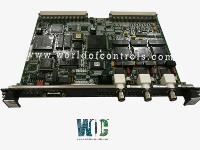
IS215VCMIH2CBB is a Communications Card developed by GE. It is a part of Mark VI control system. Its primary function is to facilitate communication among Input/Output (I/O) cards within the system and with other interconnected modules and components.
Features
- Communication Capabilities: The VCMI VME Communication board enables seamless communication between I/O cards mounted on the VME backplane, expansion racks, I/O backup protection modules, triple redundant control modules, and the primary processor module. It serves as a crucial link, ensuring smooth data exchange and coordination between different components of the control system.
- Indicator LEDs: Positioned on the front faceplate are four indicator LEDs, providing vital status information for system monitoring and diagnostics. These LEDs offer insights into the operational status of the VCMI module, allowing users to interpret system health and performance at a glance.
- Port Connections: Equipped with four port connections integrated into its front faceplate.
- An RS-232C Serial port featuring a D-style plug connector facilitates serial communication.
- Three IONet 10Base2 Ethernet ports, each accompanied by LED indicators labeled TX, RX, or CD.
- These port connections enable versatile connectivity options, allowing the module to communicate efficiently with external devices and networks.
- In addition to the port connections, the board features LED indicators labeled Status, Fail, Run, and numerical values (1, 2, 4, and 8).
- The Status, Fail, and Run indicators provide real-time feedback on system status and performance.
- The numerical LED indicators offer further insights and diagnostics capabilities, enhancing the overall monitoring and troubleshooting capabilities of the VCMI module.
- A reset switch (push button) is positioned above the Status LED, facilitating manual reset operations when necessary.
Communication
- Ethernet Ports: Equipped with three IONet 10 Base2 Ethernet ports, each having BNC connectors. These ports allow for reliable network communication between the control system’s components, providing a backbone for data transfer.
- Data Transfer Rate: The card supports a transfer rate of 10 Mbits/sec, which ensures steady and adequate communication speed for industrial applications.
- VME Bus Support: The card supports VME bus block transfers, facilitating high-speed data exchange between the communication card and other VME-compatible modules within the system. This enables efficient interaction between different components and ensures the system can handle large data volumes effectively.
- RS-232C Serial Port: The card features an RS-232C Serial port with a male D style connector, a standard communication interface used for serial data transfer. It supports multiple baud rates: 9600, 19,200, and 38,400 bits/sec, providing flexibility for different applications that require serial communication, such as connecting peripheral devices or enabling remote control and monitoring.
- Parallel Port: Provides a parallel port, capable of supporting eight-bit bi-directional communication. This port operates in EPP (Enhanced Parallel Port) Version 1.7 mode, compliant with the IEEE 1284-1994 standard. The parallel port allows fast data transfer between devices and the control system, making it ideal for applications that require efficient bulk data exchange, such as interfacing with sensors, actuators, or other external equipment.
The WOC team is always available to help you with your Mark VI requirements. For more information, please contact WOC.
Frequently Asked Questions
What is IS215VCMIH2CBB?
It is a Communications Card developed by GE under the Mark VI series.
What power supply buses are monitored within the system?
The internal 5 V, 12 V, 15 V, and 28 V power supply buses are actively monitored and alarmed to ensure system stability and reliability.
What are the default alarm settings for the power supplies?
The alarm settings for the monitored power supplies are configurable, typically set at 3.5 percent for most voltages. However, the 28 V supplies have a slightly higher alarm threshold, set at 5.5 percent.
What diagnostic signals are monitored from the power distribution module (PDM)?
Diagnostic signals from the power distribution module (PDM), connected through J301, undergo monitoring. Ground fault detection and over/under voltage on the P125 V bus. Two differential 5V dc analog inputs, labeled as P28A and PCOM, utilized for external monitor circuits. Digital inputs, providing additional diagnostic information.
