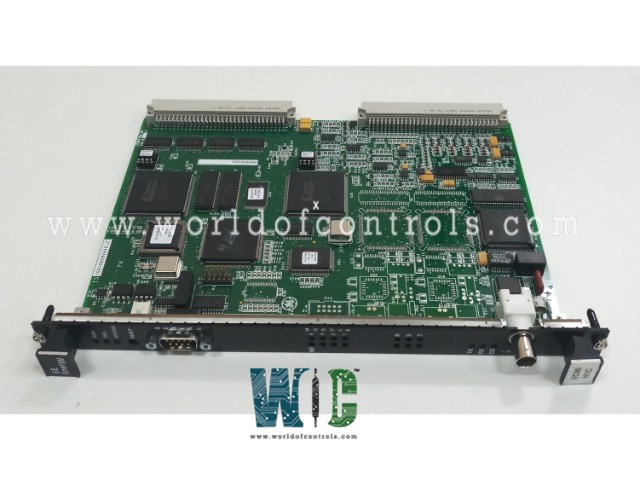
SPECIFICATIONS
Part No.: IS215VCMIH1CB
Manufacturer: General Electric
Country of Manufacture: United States of America (USA)
Board Type: 6U high VME board, 0.787 inch wide
Processor: Texas Instruments TMS320C32
Flash memory: 128k x 8
Product Type: Bus Master Controller Board
Availability: In Stock
Series: Mark VI
Functional Description
IS215VCMIH1CB is a Bus Master Controller Board developed by GE. It is a part of Mark VI control system. The VCMI serves as a pivotal communication interface within the control system, facilitating seamless interaction between the controller and the I/O boards. Moreover, it acts as the conduit for communication within the system control network, commonly referred to as IONet. In its role as the VME bus master, the VCMI assumes command in both the control and I/O racks, orchestrating data flow and coordination among the interconnected components.
Features
- One of the key responsibilities of the VCMI is the management of board identities within the rack, along with their corresponding terminal boards. This entails assigning and overseeing unique identifiers for each board, ensuring efficient communication and interaction throughout the system. By overseeing these crucial aspects of communication and coordination, the VCMI plays a central role in maintaining the integrity and functionality of the control system.
- In the context of a larger system featuring remote I/O racks, the architecture incorporates multiple IONets, each capable of accommodating several I/O racks. While the depiction presented illustrates only a single rack, it serves as a representative example of the broader system configuration. Notably, all I/O channels denoted as R, S, and T maintain uniformity in terms of the types of I/O boards installed and the array of points they support.
- The design philosophy behind this setup prioritizes scalability and consistency across the I/O infrastructure. By standardizing the I/O channels with identical configurations and capabilities, the system ensures seamless interoperability and ease of management across multiple racks and IONets. This uniformity simplifies the deployment and maintenance processes, facilitating efficient operation and enhancing overall system reliability.
- While the illustrated scenario showcases a single I/O rack within the larger system framework, it exemplifies the modular and scalable nature of the architecture, capable of accommodating additional racks and expanding I/O capacity as required. This approach offers flexibility and adaptability to evolving operational needs, making it well-suited for diverse industrial applications requiring robust and reliable I/O solutions.
Diagnostics
- Monitoring Power Supply Buses: The system meticulously monitors internal power supply buses, including the 5 V, 12 V, 15 V, and 28 V buses. Any deviations from predefined voltage thresholds trigger alarms, enabling swift detection and resolution of potential issues.
- Configurable Alarm Thresholds: Alarm thresholds for voltage deviations are configurable, typically set at 3.5 percent for most buses. However, the 28 V supplies have a threshold of 5.5 percent, ensuring appropriate sensitivity to voltage variations.
- Power Distribution Module (PDM) Signals: Diagnostic signals from the PDM are also closely monitored. These signals encompass various parameters such as ground fault detection, over/under voltage monitoring on the P125 V bus, and digital inputs, providing a comprehensive view of the power distribution system's health.
- External Monitoring Circuits: The PDM facilitates external monitoring circuits through differential ±5V dc analog inputs (P28A and PCOM), enhancing the system's diagnostic capabilities by integrating additional monitoring functionality.
Product Attributes
- Board Specifications: It is a 6U high VME (Versatile Module Eurocard) board, measuring 0.787 inches wide. This standardized form factor ensures compatibility with VME-based systems and allows for efficient integration into the control system's architecture.
- Processor: The board is powered by a Texas Instruments TMS320C32 32-bit digital signal processor (DSP). This processor is designed to handle the real-time, high-speed data processing tasks required by the control system, allowing for quick responses and accurate control actions within the system.
- Memory: The board includes dual-port memory, which enables efficient communication between different processors in the system without conflicts.
- 32 Kbytes in 32-bit transfer configuration for fast access and data transfer.
- SRAM (Static RAM) with 256k x 32 bits of memory, ensuring fast data storage and retrieval operations.
- Flash memory for persistent storage, with 512k x 8 memory for VCMIH_B, 4096k x 8 memory for VCMIH_C.
- Communication: Includes one IONet 10Base2 Ethernet port, using a BNC connector and capable of data transfer speeds up to 10 Mbits/sec. The VCMI supports block transfers on the VME bus, which facilitates high-speed data communication between different boards in the control system. The board also includes a serial port for communication with other devices or systems, with a D-style plug connector and a baud rate of 9600.
- Frame Rate: The board supports a flexible frame rate to accommodate different system configurations.
- 10 ms (100 Hz) frame rate for simplex configurations.
- 40 ms (25 Hz) frame rate for TMR (Triple Modular Redundant) configurations, ensuring higher reliability through redundancy.
- The 20 ms and 80 ms frame rates are application-dependent and can be adjusted based on specific system requirements for data processing speed.
The WOC team is always available to help you with your Mark VI requirements. For more information, please contact WOC.
Frequently Asked Questions
What is IS215VCMIH1CB?
It is a Bus Master Controller Board developed by GE under the Mark VI series.
What does the diagnostics feature of the system primarily monitor?
The diagnostics feature primarily monitors critical internal power supply buses, including the 5 V, 12 V, 15 V, and 28 V buses.
How are alarm thresholds configured for voltage deviations?
Alarm thresholds for voltage deviations are typically set at 3.5 percent for most buses. However, the 28 V supplies have a threshold of 5.5 percent, ensuring appropriate sensitivity to voltage variations.
What signals are monitored from the Power Distribution Module (PDM)?
The system monitors various diagnostic signals from the PDM, including ground fault detection, over/under voltage on the P125 V bus, two differential 5V dc analog inputs (P28A and PCOM) for external monitor circuits, and digital inputs.
