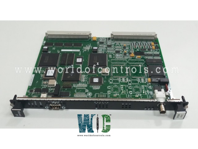
World Of Controls understands the criticality of your requirement and works towards reducing the lead time as much as possible.
IS215VCMIH1CA - VME Bus Master Controller Board is available in stock which ships the same day.
IS215VCMIH1CA - VME Bus Master Controller Board comes in UNUSED as well as REBUILT condition.
To avail our best deals for IS215VCMIH1CA - VME Bus Master Controller Board, contact us and we will get back to you within 24 hours.
SPECIFICATIONS:
Part Number: IS215VCMIH1CA
Manufacturer: General Electric
Series: Mark VI
Product Type: VME Bus Master Controller Board
Processor: TMS320C32 32-bit
Output channels: 18 buffered outputs
Common Mode Voltage Range: ±5 V
Body Type: 6U high VME board
Memory: Flash memory, 128k x 8
Film Rate: 10 ms (100 Hz) for simplex
Frame Rate: 40 ms (25 Hz) for TMR
Dimensions: 17.8 cm Wide x 33.02 cm High
Operating temperature: 30 to 65 °C
Repair: 3-7 Day
Availability: In Stock
Country of Origin: United States
Manual: GEH 6421H
FUNCTIONAL DESCRIPTION:
IS215VCMIH1CA is a VME Bus Master Controller Board manufactured and designed by General Electric as part of the VI Series used in GE Speedtronic Gas Turbine Control Systems. The VCMI is the communication interface between the controller and the I/O boards, and the communication interface to the system control network, known as IONet. VCMI is also the VME bus master in the control and I/O racks and manages the IDs for all the boards in the rack and their associated terminal boards. The VME Bus Master Controller Board facilitates connections between controllers and I/O modules. A VCMI board within the VME rack enables bi-directional communication between the I/O processor boards and the controller. Communication with other system components, such as an operator interface or PLC, is handled via the controller’s Ethernet port. Additional PLC I/O can be connected through the controller’s Genius port. The system uses a low-voltage version of the standard VME rack power supply, operating on 24V DC power.
The signal conditioning on DIN-type terminal boards is identical to that on T-type terminal boards, and the same I/O specifications apply. However, these boards do not support TMR, and there are variations in the number of inputs and outputs, along with different grounding requirements. Space is optimized through the use of high-density Euro-Block terminal blocks, which are permanently mounted. These terminals can hold either two #14 wires or one #12 wire, with #18 AWG being the most commonly used wire size.
OPERATION:
The controller software is specifically tailored for applications involving steam, gas, land-marine derivatives (LM), or balance of plant (BOP) systems. It can process up to 100,000 rungs or blocks per second, assuming a typical collection of average-sized blocks. The controller can synchronize with the VCMI communication board's clock within 100 microseconds using an external clock interrupt.
The VCMI board utilizes the VME bus to transmit and receive external data between the control system database (CSDB) and the controller. In a simplex system, this data consists of inputs and outputs from the I/O boards. For a TMR system, the data includes inputs from the input boards, individual inputs from simplex boards, computed outputs for voting by the output hardware, and internal state information that must be exchanged between controllers.
INSTALLATION:
A control module consists of two main components: the controller and the VCMI. Three rack options are available, including the GE Fanuc integrator’s rack shown in the accompanying figure and the two Mark VI rack sizes detailed in the "VCMI - Bus Master Controller" section. The shorter GE Fanuc rack is used solely for standalone modules with remote I/O, while the longer Mark VI racks can accommodate both local and remote I/O. The cooling fan's placement, either above or below the controller, depends on the specific rack being used. For standalone control modules in a GE Fanuc integrator’s rack, a VDSK board is required to provide fan power and identify the rack via an ID connection.
WOC has the largest stock of OEM replacement parts for GE Speedtronic Gas Turbine Control Systems. We can also repair your faulty boards and supply unused and rebuilt boards backed up with a warranty. Our team of experts is available round the clock to support your OEM needs. Our team of experts at WOC is happy to assist you with any of your automation requirements. For pricing and availability on parts and repairs, kindly contact our team by phone or email.
How does the diagnostic system enhance system reliability?
By actively monitoring power supply voltages and diagnostic signals, the system can detect deviations from normal operating conditions early, allowing for timely corrective actions to maintain system integrity and reliability.
What types of racks are available for control modules?
The GE Fanuc integrator rack and two Mark VI racks come in different sizes. The shorter GE Fanuc rack supports only standalone modules with remote I/O, while the longer Mark VI racks support both local and remote I/O.
What type of data is transmitted in a TMR system?
In a TMR system, data includes inputs from the input boards, singular inputs from simplex boards, computed outputs for voting by the output hardware, and internal state information exchanged between controllers.